Inter-Integrated Circuit Peripherals
UG0331 User Guide Revision 15.0 540
15.2.1.3 Address Comparator
When a master transmits a slave address on the bus, the address comparator checks the 7-bit slave
address with its own slave address. If the transmitted slave address does not match, the address
comparator compares the first received byte with the general call address (0x00). If the address
matches, the Status register is updated. The general call address is used to address each device
connected to the I2C-bus.
15.2.1.4 Serial Clock Generator
In Master mode, the serial clock generator generates the serial clock line (SCL). The clock generator is
switched off when I
2
C is in Slave mode. Refer to the I
2
C Clock Requirements, page 541 for details on the
baud rate clock (BCLK).
15.2.2 Port List
The following table lists the various I
2
C signals. The letter X is used as a placeholder for 0 or 1 in register
and signal descriptions.
15.2.2.1 I
2
C Byte Transfer
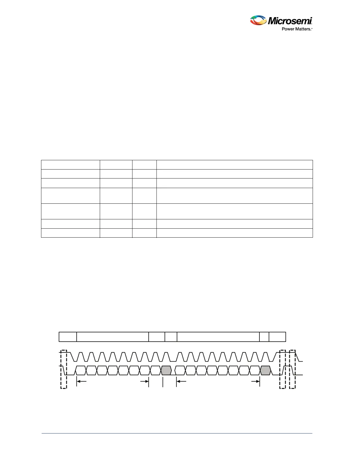
A typical I
2
C 8-bit data transfer cycle is shown in the following figure. A start condition is signaled when
the SDA line goes Low while the SCL line is High. After a start condition, the master transmits the 7-bit
slave address followed by a direction bit, which is decoded and acknowledged (ACK) by the slave.
Following the address phase, multiple bytes can be transferred with an ACK for each byte. The end of
the transaction is signaled by a stop condition. The stop condition is signaled by the SDA line asserted
High while the SCL line is High.
When the I
2
C peripheral is in a receiver (Master or Slave) mode, it may acknowledge or ignore the data
sent by the transmitter. The I
2
C peripheral must send a no-acknowledge (NACK) bit during the
acknowledge cycle on the bus to disable the data transfer by signaling the stop condition.
Figure 230 • 8-bit Data Transfer Cycle
Table 517 • I
2
C Interface Signals
Name Type Polarity Description
I2C_X_SCL Input/Output High Serial clock
I2C_X_SDA Input/Output High Serial data
I2C_X_SMBALERT_NI Input High Input interrupt signal; used in Master mode to monitor whether the
slave wants to force communication with the master.
I2C_X_SMBALERT_NO Output High Output interrupt signal; used in Slave mode if the slave wants to
force communication with the master.
I2C_X_SMBSUS_NI Input High Input Suspend Mode signal; used in I
2
C Slave mode.
I2C_X_SMBSUS_NO Output High Output Suspend Mode signal; used in I
2
C Master mode.
SCL
SDA
ACK
S
Start
S
Start
P
Stop
7-bit Slave Address
8 -bit Data
MSB LSB ACK
Direction
bit
Start
Slave Address
Direction
ACK
Data
ACK
Stop
7-bit
1-bit
8-bit
1-bit to