MMUART Peripherals
UG0331 User Guide Revision 15.0 489
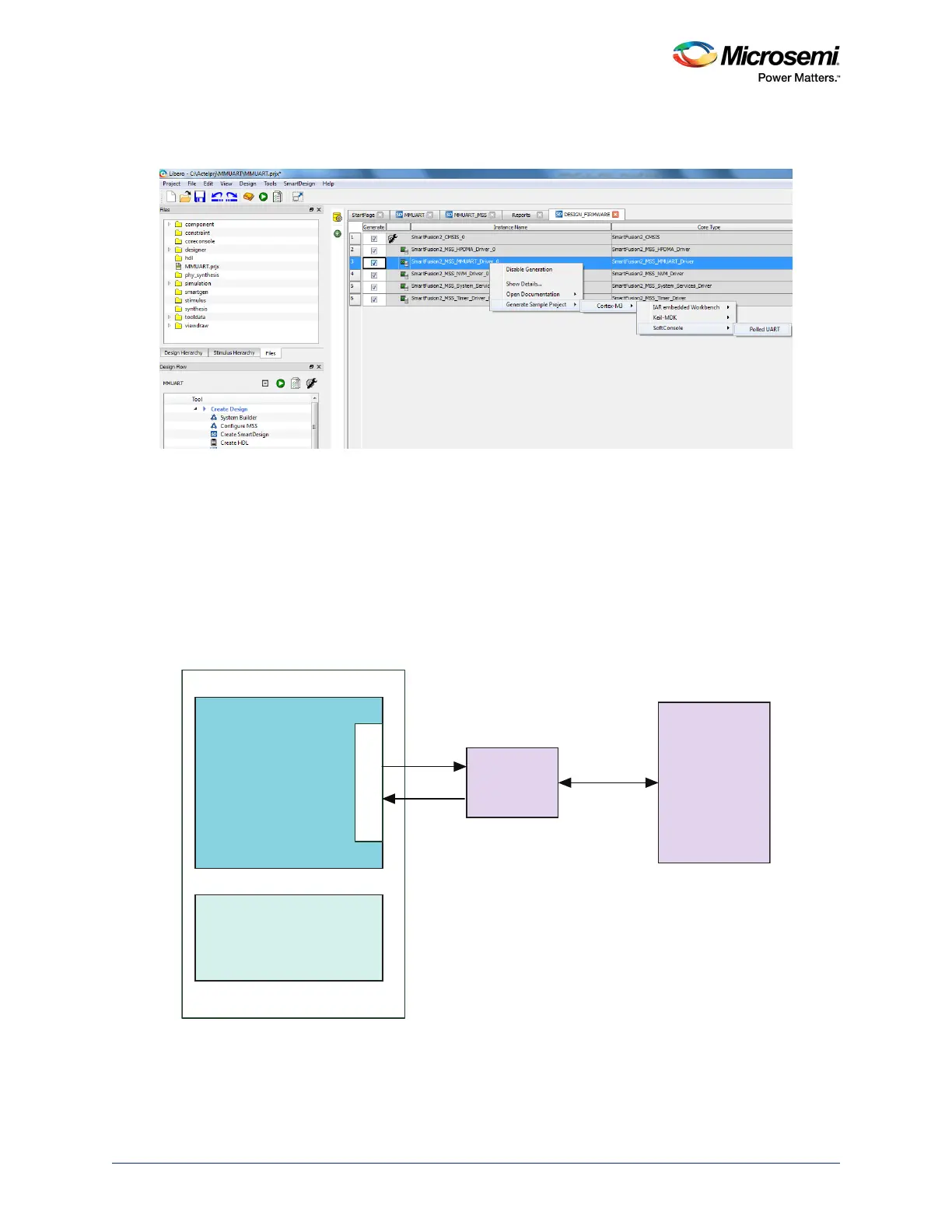
7. For more information on MMUART usage, the sample projects are available and can be generated
as shown in the following figure.
Figure 202 • MMUART Sample Project
Note: The MSS MMUART does not support full behavioral simulation models. Refer to SmartFusion2 MSS
BFM Simulation User Guide for more information.
13.3.2 MMUART Use Models
13.3.2.1 Use Model: Communicating with Host PC through MMUART Peripheral
Interface
This use model explains the configuration of MSS MMUART to communicate with the Host PC
Hyper-Terminal program.
Figure 203 • Setup to Communicate With Host PC Through MMUART Interface - Block Diagram
Follow Design Flow, page 486 to configure MMUART_0 in the application.
HyperTerminal
program running
on Host PC
SmartFusion2
MMUART_0
MSS
FABRIC
RS 232
Transceiver
USB-UART
cable