Cortex-M3 Processor (Reference Material)
UG0331 User Guide Revision 15.0 123
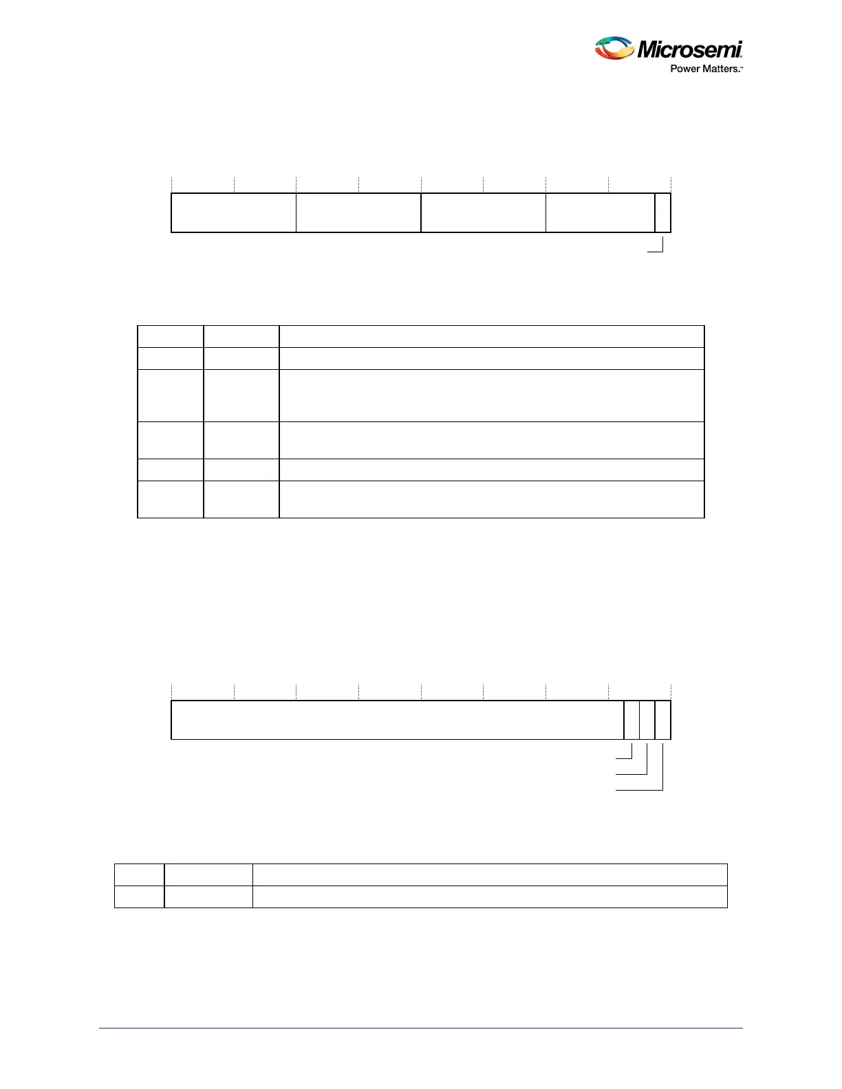
3.7.4.1 MPU Type Register
The MPU_TYPE register indicates whether the MPU is present, and if so, how many regions it supports.
See the register summary in Ta ble 77 , page 123 for its attributes. The bit assignments are:
Figure 50 • MPU_TYPE Register Bit Assignments
3.7.4.2 MPU Control Register
The MPU_CTRL register:
• enables the MPU
• enables the default memory map background region
• enables use of the MPU when in the HardFault, Non-maskable Interrupt (NMI), and FAULTMASK
escalated handlers.
See the register summary in Ta ble 77 , page 123 for the MPU_CTRL attributes. The bit assignments are:
Figure 51 • MPU_CTRL Register Bit Assignments (continued)
Table 78 • MPU_TYPE Register Bit Assignments
Bits Name Function
[31:24] Reserved.
[23:16] IREGION Indicates the number of supported MPU instruction regions.
Always contains 0x00. The MPU memory map is unified and is described by
the DREGION field.
[15:8] DREGION Indicates the number of supported MPU data regions:
0x08=Eight MPU regions.
[7:0] Reserved.
[0] SEPARATE Indicates support for unified or separate instruction and date memory maps:
0: unified
Table 79 • MPU_CTRL Register Bit Assignments
Bits Name Function
[31:3] Reserved.
5HVHUYHG
,5(*,21 '5(*,21 5HVHUYHG
6(3$5$7(
5HVHUYHG
+)10,(1$
(1$%/(
35,9'()(1$