MMUART Peripherals
UG0331 User Guide Revision 15.0 494
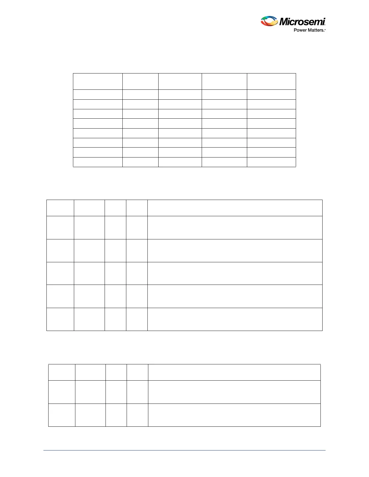
The following table contains the list of baud rates and corresponding values of DFR and DMR+DLR
registers.
13.4.5 Interrupt Enable Register (IER)
13.4.6 Multi-Mode Interrupt Enable Register (IEM)
Table 474 • Baud Rates and Divisor Values for the 18.432 MHz Reference Clock
Baud Rate Divisor
DLR + DMR
Integer Divisor
DFR Fractional
Divisor in 64
th
Percent Error
50 23,040 23,040 0 0.00000%
75 15,360 15,360 0 0.00000%
110 10,472.72 10,472 47 0.00007%
134.5 8,565.05 8,565 4 0.00008%
150 7,680 7,680 0 0.00000%
2,000 576 576 0 0.00000%
38,400 30 30 0 0.00000%
56,000 21.57 21 37 0.03255%
Table 475 • IER
Bit
Number Name R/W
Reset
Value Description
[7:4] Reserved R/W 0 Software should not rely on the value of a reserved bit. To provide
compatibility with future products, the value of a reserved bit should be
preserved across a read-modify-write operation.
3 EDSSI R/W 0 Modem status interrupt enable
0: Disabled (default)
1: Enabled
2 ELSI R/W 0 Receiver line status interrupt enable
0: Disabled (default)
1: Enabled
1 ETBEI R/W 0 Transmitter holding register empty interrupt enable
0: Disabled (default)
1: Enabled
0 ERBFI R/W 0 Enables received data available interrupt
0: Disabled (default)
1: Enabled
Table 476 • IEM
Bit
Number Name R/W
Reset
Value Description
[7:5] Reserved R/W 0 Software should not rely on the value of a reserved bit. To provide
compatibility with future products, the value of a reserved bit should be
preserved across a read-modify-write operation.
4 ELINSI R/W 0 Enables the LIN sync detection interrupt
0: Disabled (default)
1: Enabled