High Performance DMA Controller
UG0331 User Guide Revision 15.0 263
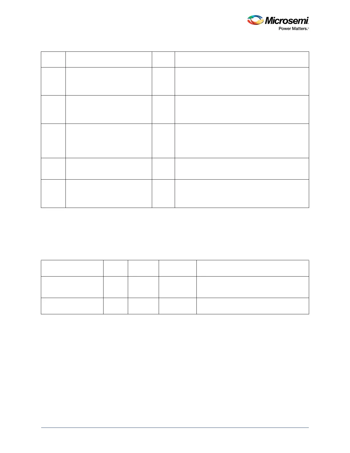
8.5 SYSREG Control Register
In addition to the specific HPDMA registers, the registers provided in Ta ble 1 73, page 263 also control
the behavior of the HPDMA peripheral. Refer to the System Register Block, page 670 for a detailed
description of each register and associated bits.
18:16 HPDMADR_WBC_CST_DBG[2:0] 0 Write buffer controller current state
001 – IDLE
010 – RUN
100 – WAIT
21:19 HPDMADR_RBC_CST_DBG[2:0] 0 Read buffer controller current state
001 – IDLE
010 – RUN
100 – WAIT
25:22 HPDMADR_RRBN_CST_DBG[3:0] 0 Round robin FSM current state
0001 – D0
0010 – D1
0100 – D2
1000 – D3
27:26 HPDMADR_DMA_CST_DBG[1:0] 0 DMA controller FSM current state
01 – IDLE
10 – RUN
31:28 Reserved 0 Software should not rely on the value of a reserved bit. To
provide compatibility with future products, the value of a
reserved bit should be preserved across a read-modify-
write operation.
Table 173 • SYSREG Control Registers
Register Name
Register
Type
Flash Write
Protect Reset Source Description
SOFT_RESET_CR RW-P Bit SYSRESET_N Bit 17 is used for HPDMA reset
’1’ – Reset HPDMA
’0’ – Release from HPDMA reset
MASTER_WEIGHT1_CR RW-P Register SYSRESET_N Bits 4:0 define round robin weight values for the
HPDMA master.
Table 172 • HPDMADR_REG (continued)
Bit
Number Name
Reset
Value Description