Reset Controller
UG0331 User Guide Revision 15.0 645
configuration. For more details on DEVRST_N timing information, refer to the DS0451: IGLOO2 and
SmartFusion2 Datasheet.
Asserting DEVRST_N does not enable the delay counter (Power on Reset Delay) in the POR circuitry.
The delay counter is operational only at power-up. When DEVRST_N is low, all user I/Os are fully tri-
stated. Although, the JTAG I/Os are still enabled, they cannot be used as the TAP controller is in reset.
The SYSRESET macro is not required to be instantiated to enable the DEVRST_N pin in the user
design. DEVRST_N is a dedicated input-only reset pad available on all the SmartFusion2 devices.
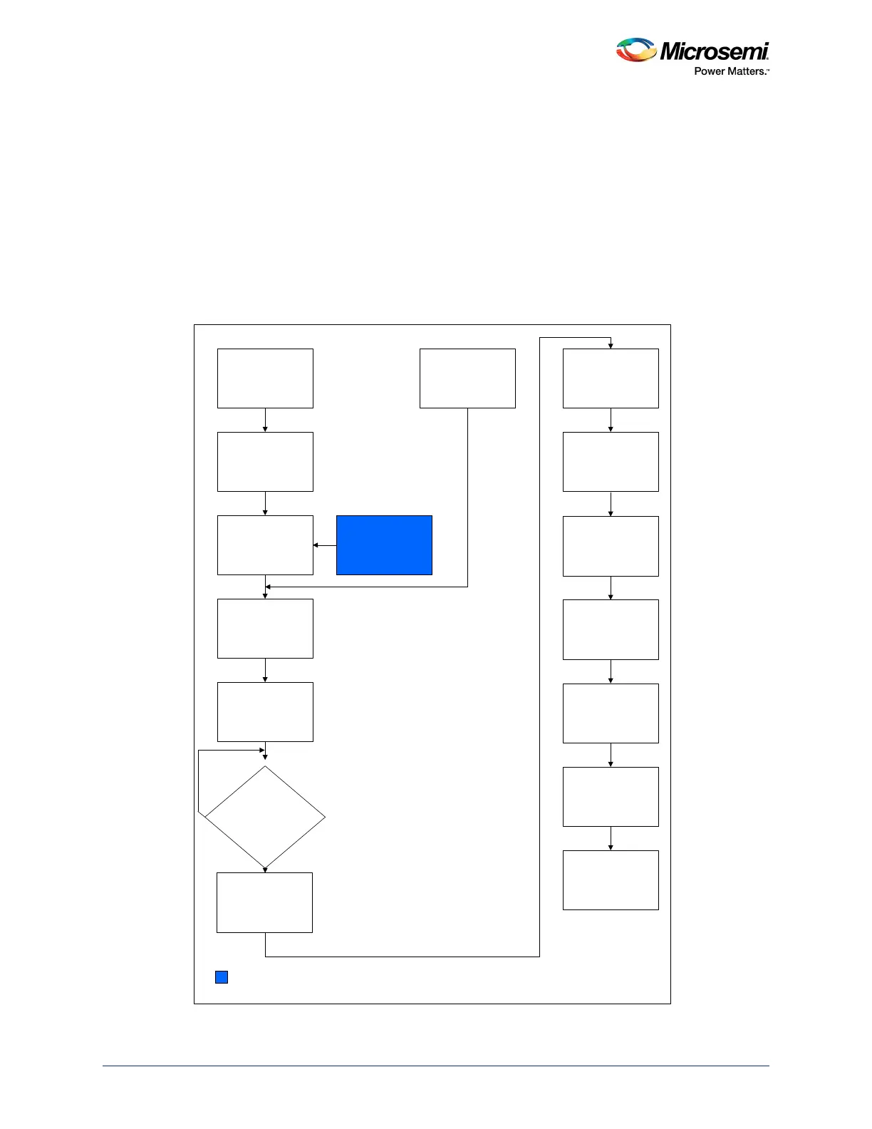
21.1.2 Power-Up to Functional Time Sequence
The following figure shows the power up to functional time sequence diagram.
Figure 279 • Power up to Functional Time Sequence Diagram
6XSSO\5DPS
9''9339'',
9''$3//
0+]5&2VFLOODWRU7XUQV
2Q
'LH5DPS
3RZHURQ5HVHW'HOD\
&RQILJXUDWLRQ
/LEHUR6R&
3RZHU2Q5HVHW
32B5(6(7B15HOHDVHG
0+]5&2VFLOODWRU*DWHG
2II
DQG
0+]5&2VFLOODWRU
7XUQV2Q
,QSXWEXIIHUHQDEOH
)DEULF3///RFN$VVHUWHG
)DEULF&&&
066UHVHW
6&B066B5(6(7B1
5HOHDVHG
03///RFN$VVHUWHG
066&&&
066WR)DEULF5HVHW
066B5HVHWB1B0)
5HOHDVHG
'(9567B1
/LEHUR6HWWLQJ
)3*$)DEULF/65$0
X65$0DQG0$7+)''5
DQG6(5'(6
7XUQ2Q
$OOPDQGDWRU\,2EDQN
VXSSOLHVDUH
SRZHUHGXS"
<HV
1R
2XWSXWEXIIHUHQDEOH
32:(5B21B5(6(7B1
6LJQDO5HOHDVHG