System Register Block
UG0331 User Guide Revision 15.0 675
22.1.1 Lock Bit File
An initial, default lock bit file can be generated by clicking Generate FPGA Array Data in the Design
Flow window.
The default file located at
<proj_location>/designer/<root>/<root>_init_config_lock_bits.txt
can be used to make the required changes.
Note: Save the file using a different name if you modify the text file to set the lock bits.
22.1.2 Lock Bit File Syntax
A valid entry in the lock bit configuration file is defined as a <lock_parameters> < lock bit value> pair
format.
The lock parameters are structured as follows:
• Lock bits syntax for a register: <Physical block name>_<register name>_LOCK
• Lock bits syntax for a specific field: <Physical block name>_<register name>_<field name>_LOCK
• The following are the physical block names (varies with device family and die):
•MSS
•FDDR
• SERDES_IF_x (where x is 0,1,2,3 to indicate the physical SERDES location) for SmartFusion2
M2S010/025/050/150 devices
• SERDES_IF2 for SmartFusion2 M2S060/090 devices (only one SERDES block per device)
Set the lock bit value to 1 to indicate that the register can be written to (unlocked) and to 0 to indicate that
the register cannot be written to (locked).
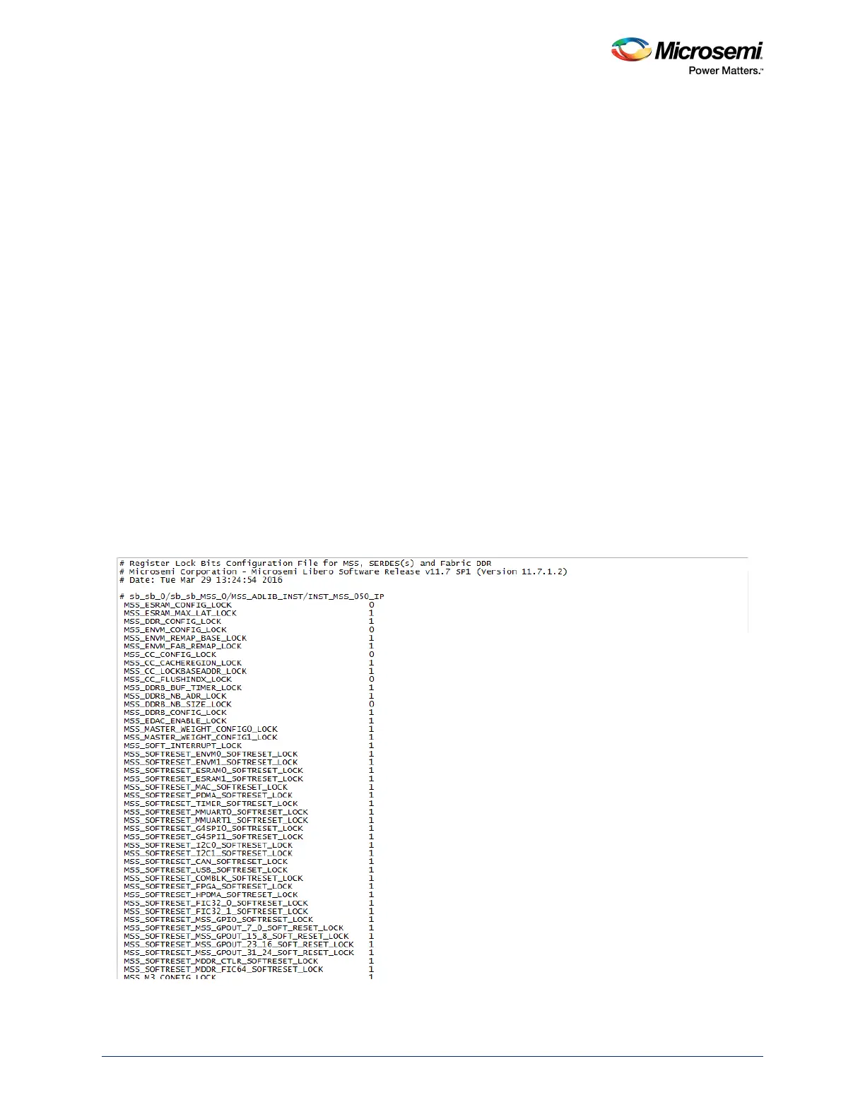
Lines starting with # or ; are comments. Empty lines are allowed in the lock bit configuration file.
The following figure shows the lock bit configuration file.
Figure 318 • Lock Bit Configuration File