MMUART Peripherals
UG0331 User Guide Revision 15.0 479
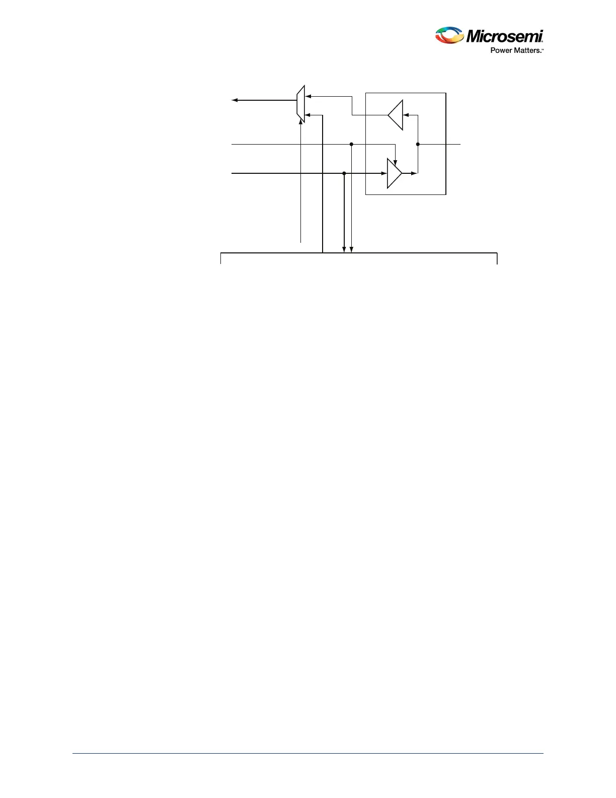
Figure 185 • Bi-Directional Synchronous Clock Configuration Options
13.2.4.2 Input Filters
MMUART provides input filters for general purposes and suppression of noise and spikes. After
resynchronization, the input filters utilize all-zero/all-one unanimous sampling technique based on the
system clock with a configurable filter length of N FFs, set by the GLR bits of the GFR Register. If all N
FFs are 0, then 0 is set on the output. Similarly, if all N FFs are 1, then 1 is set on the output. The input
filters may be bypassed by setting GLR to 0 in which case only two resynchronize flip-flops are used.
Setting the GLR value to 1 adds a metastability flip-flop and provides no spike filtering. GLR values 2 to 7
further filter the spikes in the output received from flip-flops. Thus, this method helps to suppress spikes
for GLR width greater than 1 APB clock cycle.
An example is shown in the following figure with GLR = 4. In all cases, positive edge and negative edge
signals are generated on the same cycle as the positive or negative edge of the resynchronized and/or
filtered output signal. Note that in order to obtain the maximum rate for synchronous UART operation (2x
APB_X_CLK), set N to zero.
Filtering in Synchronous mode is still possible, but the sampling rate would have to be decreased to less
than the filter length.
SCK
PAD
FABRIC I/F
SCK_DPI_sel
SCK_fabric
MMUART_X_SCK_IN
MMUART_X_SCK_OUT
MMUART_X_E_MST_SCK