Fabric Interface Controller
UG0331 User Guide Revision 15.0 763
24.4 Timing Diagrams
The timing diagrams contained in this section show AHB-Lite non-sequential transfers with 32 bits as the
transfer size.
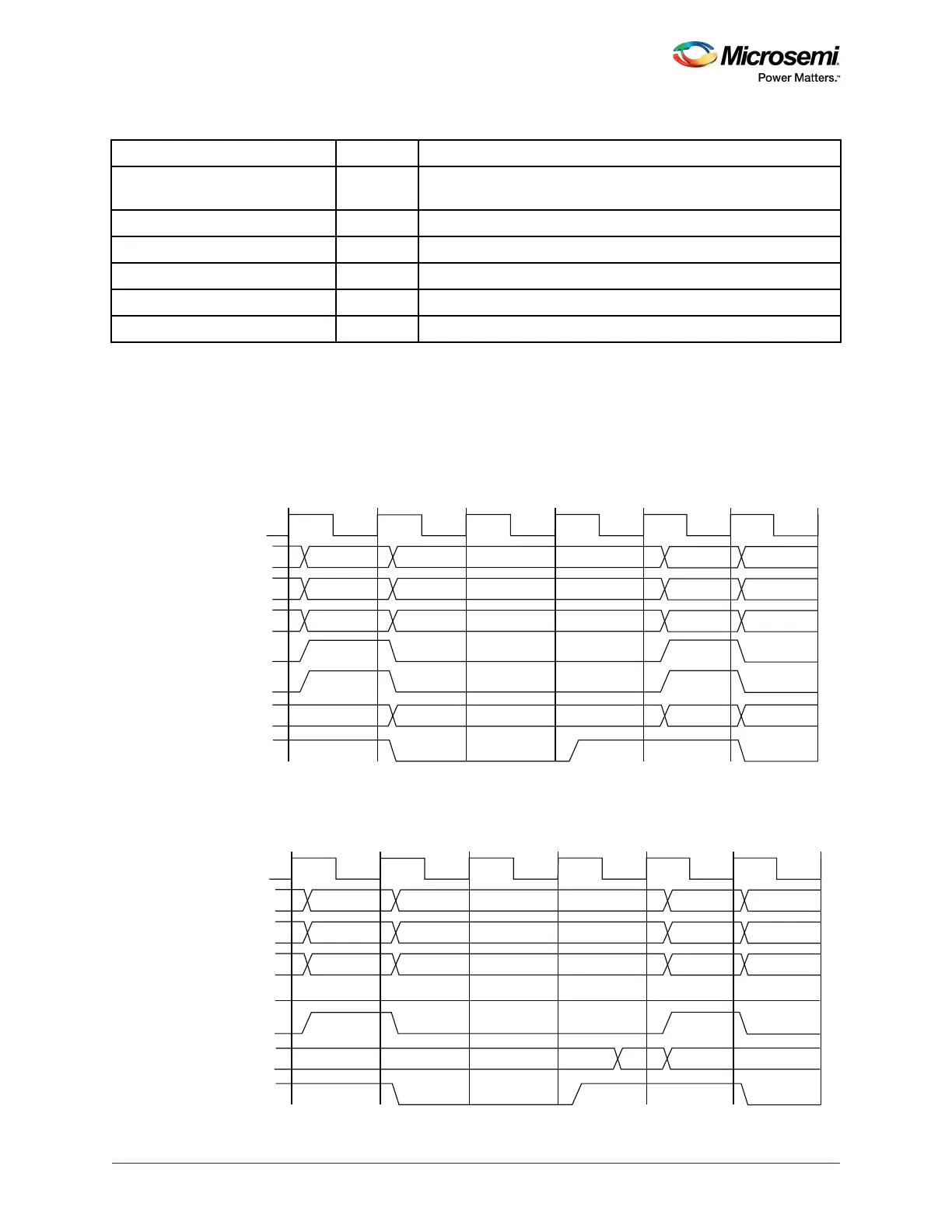
The following diagram shows the AHB-Lite bus signals from fabric interface controller to the fabric slave
for a write transaction in Bypass mode.
Figure 329 • AHB-Lite Bus Signals from FIC to the Fabric Slave for a Write Transaction in Bypass Mode
The following diagram shows the AHB-Lite bus signals from the fabric interface controller to the fabric
slave for a read transaction in Bypass mode.
Figure 330 • AHB-Lite Bus Signals from FIC to the Fabric Slave for a Read Transaction in Bypass Mode
FIC_X_AHB_M_HREADY In Indicates that a transfer has completed on the bus. The fabric slave
can drive this signal Low to extend a transfer.
FIC_X_AHB_M_HWDATA [31:0] Out Indicates AHB-Lite write data to the fabric slave.
FIC_X_AHB_M_HRDATA [31:0] In Indicates AHB-Lite read data from the fabric slave.
FIC_X_AHB_M_HRESP In Indicates AHB-Lite transfer response from the fabric slave.
FIC_X_AHB_M_HSIZE [1:0] Out Indicates AHB-Lite transfer size to the fabric slave.
FIC_X_AHB_M_HTRANS [1:0] Out Indicates AHB-Lite transfer type to the fabric slave.
Table 780 • Fabric Interface Controller Port List (continued)
Port Name Direction Description
T1 T2 T3 T4 T5 T6 T7
A
A + 4
00
00
00
00
00
00
10
10
10
10
FIC_X_AHB_M_HCLK
FIC_X_AHB_M_
HADDR[31:0]
FIC_X_AHB_M_HTRANS
FIC_X_AHB_M_HSIZE
FIC_X_AHB_M_HWRITE
FIC_X_AHB_M_HSEL
FIC_X_AHB_M_HWDATA[31:0]
FIC_X_AHB_M_HREADY
Data (A) Data (A+4)
T1 T2 T3 T4 T5 T6 T7
A
A + 4
00
00
00
00
00
00
10
10
10
10
FIC_X_AHB_M_HCLK
FIC_X_AHB_M_
HADDR[31:0]
FIC_X_AHB_M_HTRANS
FIC_X_AHB_M_HSIZE
FIC_X_AHB_M_HWRITE
FIC_X_AHB_M_HSEL
FIC_X_AHB_M_HRDATA[31:0]
FIC_X_AHB_M_HREADY
Data (A)