MSS GPIO
UG0331 User Guide Revision 15.0 572
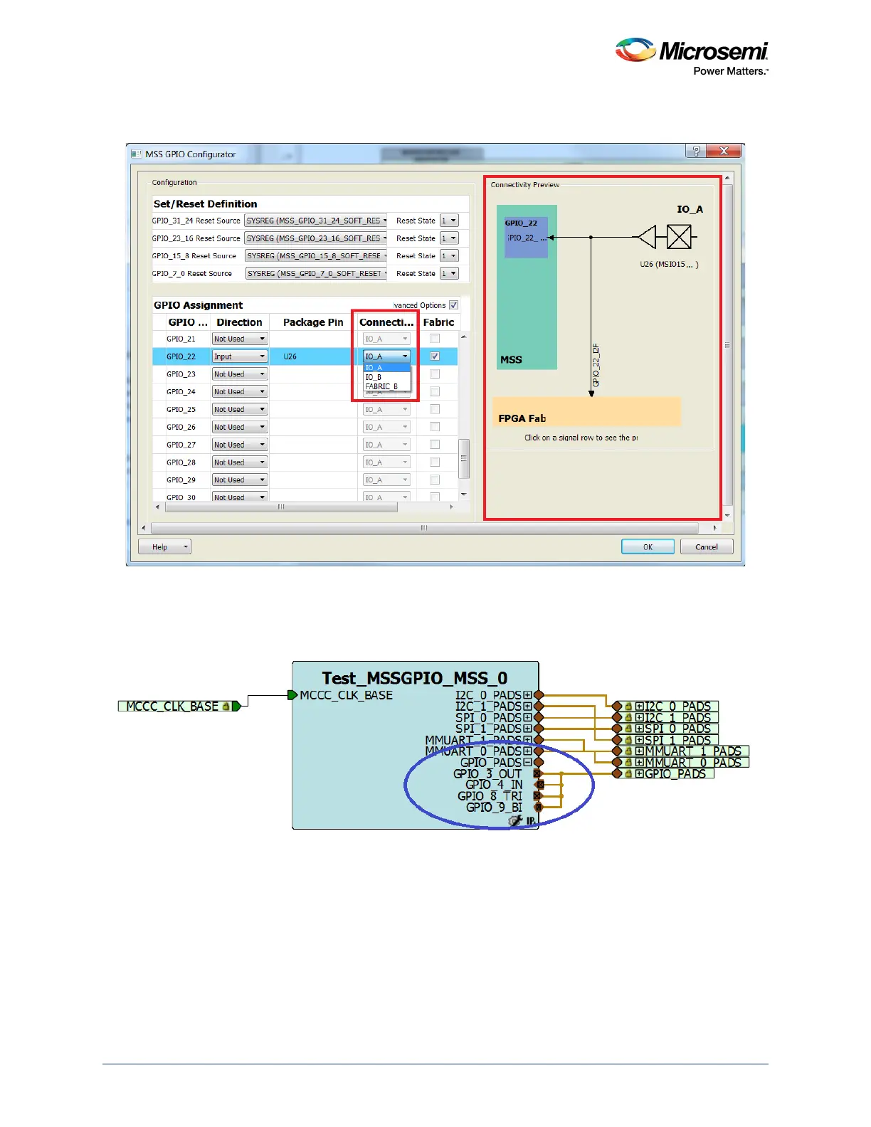
The following figure shows a graphical view of the current connections for the highlighted GPIO signal.
Figure 247 • Connectivity Preview
Step 3
The configured GPIO signals are shown in the following figure.
Figure 248 • GPIO Signals
Step 4
To generate a component, click the Generate Component shortcut in MSS configurator or select
SmartDesign > Generate Component. The firmware driver folder and SoftConsole workspace will be
included in the design project.
Step 5
Click Generate Bitstream under Program Design to complete the *.fdb file generation.