Cache Controller
UG0331 User Guide Revision 15.0 134
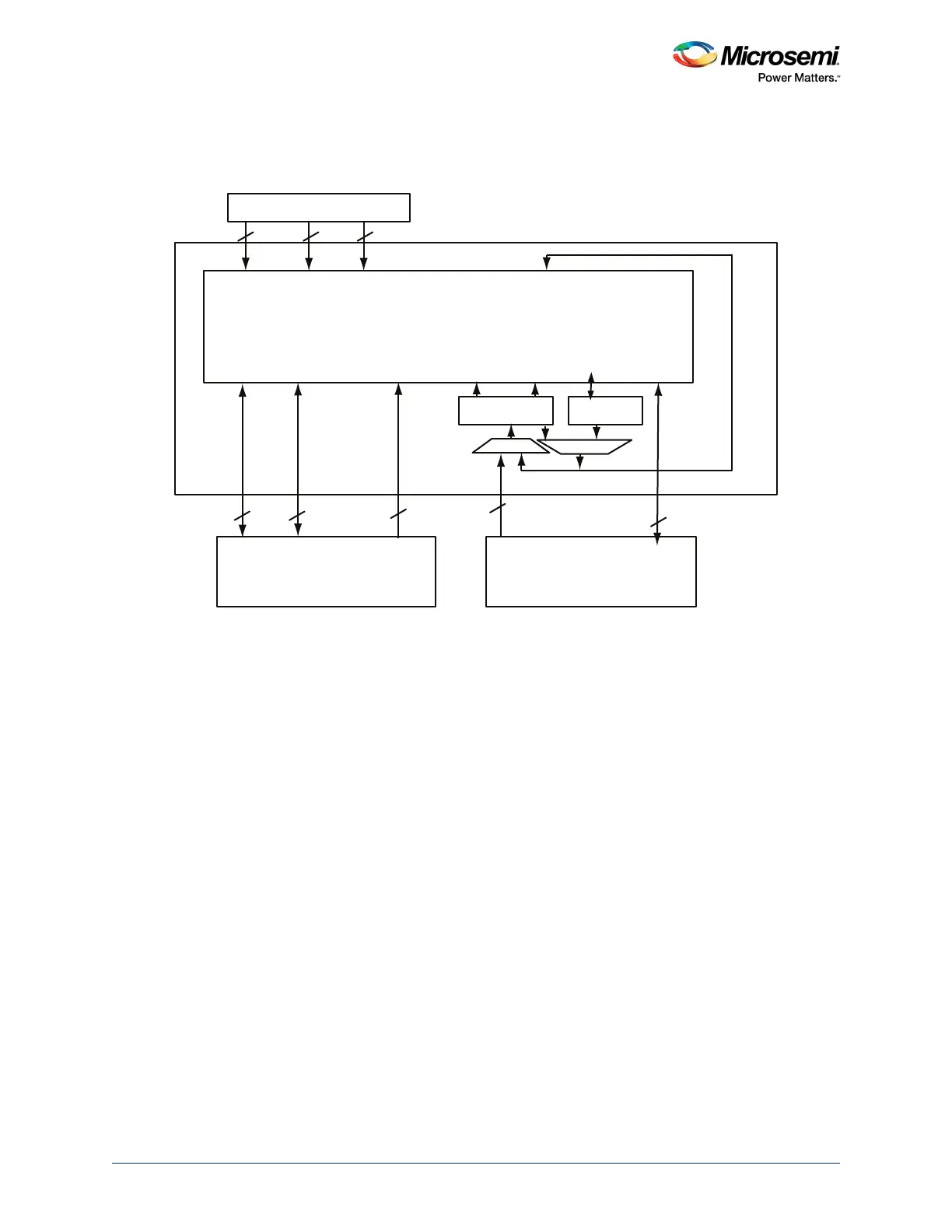
4.2 Functional Description
The following figure depicts all sub-blocks in the Cache Controller block.
Figure 57 • Cache Controller Block Diagram
The Cache Controller consists of two primary components:
• Cache Matrix
• Cache Engine
4.2.1 Cache Matrix
The cache matrix is a multi-layer AHB-Lite switch matrix. It takes care of the connectivity between
masters and slaves, arbitration for slaves, memory mapping between main memory (eNVM, eSRAM, or
DDR), and Cache Memory. The masters and slaves in the AHB matrix are referred to as mirrored
masters (MM) and mirrored slaves (MS).
One master can access a slave at the same time another master accesses another slave. If more than
one master attempts to access the same slave simultaneously, arbitration is performed. Each of the slave
devices contains an arbiter, which manages accesses when more than one master attempts to access a
slave at the same time.
4.2.2 Memory Mapping
The following sections explain memory mapping for eNVM, eSRAM, and DDR address spaces to cache
regions.
32 32 32
32 32 32
128 32
Cortex-M3 Microcontroller
AHB Bus Matrix
MSS DDR Bridge
MM 0
D
MM 1
I
MM 2
S
MM 3
C
D ( R W )
MS0
S(RW)
MS1
IC ( R )
MS2
Cache Matrix (4 x 7)
Cache Engine
AHB to
MEM DEC
D (RW)
System Controller
Bus (RW)
IC(R) IDC ( R ) D(W)/SG ( RW )
To cache memory
MM - Mirrored Master MS - Mirrored Slave
DSG - Data System and System Controller Bus
IDC - Icode and DCode Cacheable I - Instruction D - Data S- System R - Read W - Write
D(R)
MS3
D(W)/
S(RW)
MS5
S(RW)
MS6
I(R)
MS4