Cortex-M3 Processor (Reference Material)
UG0331 User Guide Revision 15.0 105
When you write to the ICSR, the effect is Unpredictable if you:
• write 1 to the PENDSVSET bit and write 1 to the PENDSVCLR bit
• write 1 to the PENDSTSET bit and write 1 to the PENDSTCLR bit.
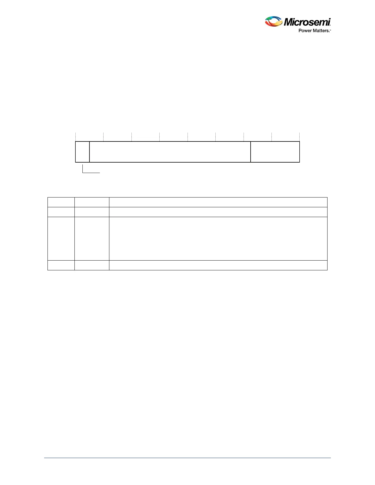
3.7.2.4 Vector Table Offset Register
The VTOR indicates the offset of the vector table base address from memory address
0x00000000
. See
the register summary in Ta bl e 50 , page 102for its attributes.
The bit assignments are:
Figure 33 • VTOR Bit Assignments
When setting TBLOFF, you must align the offset to the number of exception entries in the vector table.
<Configure the next statement to give the information required for your implementation, the statement
reminds you of how to determine the alignment requirement.> The minimum alignment is 32 words,
enough for up to 16 interrupts. For more interrupts, adjust the alignment by rounding up to the next power
of two. For example, if you require 21 interrupts, the alignment must be on a 64-word boundary because
the required table size is 37 words, and the next power of two is 64.
Table alignment requirements mean that bits [6:0] of the table offset are always zero.
3.7.2.5 Application Interrupt and Reset Control Register
The AIRCR provides priority grouping control for the exception model, endian status for data accesses,
and reset control of the system. See the register summary in Tab le 50 , page 102 and Tabl e 55 , page 107
for its attributes.
To write to this register, you must write
0x5FA
to the VECTKEY field, otherwise the processor ignores the
write.
1. This is the same value as IPSR bits[8:0], see Interrupt Program Status Register, page 23.
Table 54 • VTOR Bit Assignments
Bits Name Function
[31:30] Reserved.
[29:7] TBLOFF Vector table base offset field. It contains bits[29:7] of the offset of the table base from the
bottom of the memory map.
Bit [29] determines whether the vector table is in the code or SRAM memory region:
0: Code
1: SRAM.
Bit [29] is sometimes called the TBLBASE bit.
[6:0] Reserved.
31 30 29 6 0
TBLOFF Reserved
Reserved
7