MSS GPIO
UG0331 User Guide Revision 15.0 577
16.4.3 MSS GPIO Definitions
16.4.4 Loopback Control Register
16.4.5 GPIO Input Source Select Control Register
Note: The Libero automatically takes care of GPIO source input selection between current IOMUXCELL and
alternate IOMUXCELL.
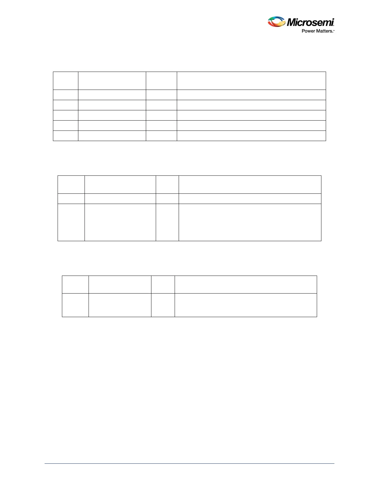
Table 541 • MSS_GPIO_DEF
Bit
Number Name
Reset
Value Description
[31:4] Reserved 0 Reserved
3 MSS_GPIO_31_24_DEF 0x1 Used to initialize GPIO bank [31:24] to 0 or 1 after reset.
2 MSS_GPIO_23_16_DEF 0x1 Used to initialize GPIO bank [23:16] to 0 or 1 after reset.
1 MSS_GPIO_15_8_DEF 0x1 Used to initialize GPIO bank [15:8] to 0 or 1 after reset.
0 MSS_GPIO_7_0_DEF 0x1 Used to initialize GPIO bank [7:0] to 0 or 1 after reset.
Table 542 • LOOPBACK_CR
Bit
Number Name
Reset
Value Description
[31:4] Reserved 0 Reserved
3 MSS_GPIOLOOPBACK 0 Controls whether internal loopback on the MSS GPIO is
enabled. Allowed values:
0: No internal loopback for MSS GPIO
1: MSS GPIO outputs are looped back to MSS GPIO
inputs
Table 543 • GPIN_SRC_SEL_CR
Bit
Number Name
Reset
Value Description
[31:0] MSS_GPINSOURCE 0 This 32-bit signal is used as select signal to generate a
GPIO input signal by selecting two output signals from
different IOMUXCELL or signals from I/O pads.