Serial Peripheral Interface Controller
UG0331 User Guide Revision 15.0 507
14.2.2.3 Motorola SPI Protocol
The Motorola SPI is a full duplex, four-wire synchronous transfer protocol which supports programmable
clock polarity (SPO) and clock phase (SPH). The state of SPO and SPH control bits decides the data
transfer modes as detailed in the following table.
The SPH control bit determines the clock edge that captures the data.
• When SPH is Low, data is captured on the first clock transition.
• Data is captured on the rising edge of SPI_CLK when SPO = 0 (Figure 206, page 508).
• Data is captured on the falling edge of SPI_CLK when SPO = 1 (Figure 209, page 509).
• When SPH is High, data is captured on the second clock transition (rising edge if SPO = 1).
• Data is captured on the falling edge of SPI_CLK when SPO = 0 (Figure 208, page 509).
• Data is captured on the rising edge of SPI_CLK when SPO = 1 (Figure 210, page 509).
The SPO control bit determines the polarity of the clock and SPS defines the slave select behavior.
• When SPO is Low and no data is transferred, SPI_CLK is driven to Low (Figure 207, page 508).
• When SPO is High and no data is transferred, SPI_CLK is driven to High (Figure 209, page 509).
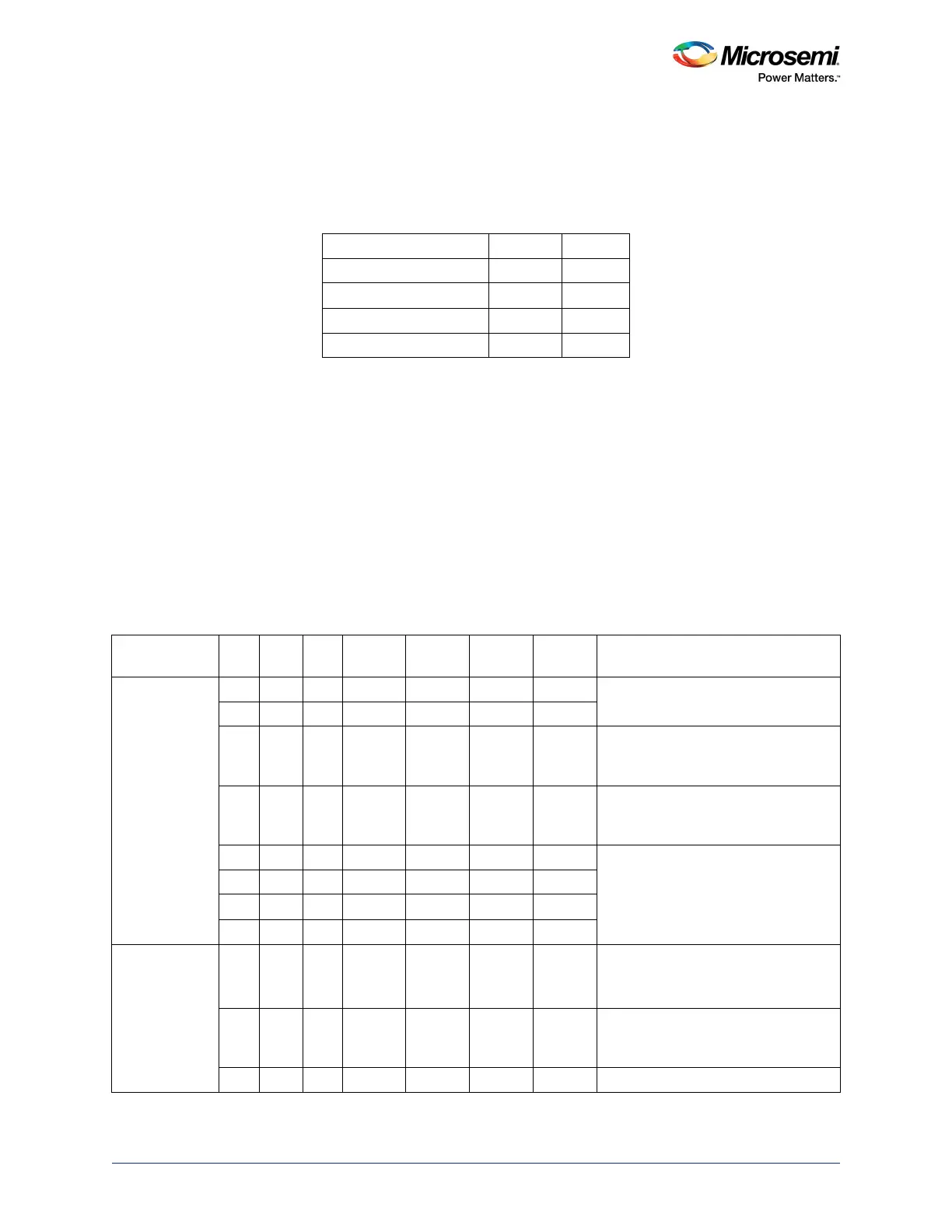
The following table summarizes the clock active edges in various SPI master modes.
Table 493 • Data Transfer Modes
Data Transfer Mode SPO SPH
Mode 0 0 0
Mode 1 0 1
Mode 2 1 0
Mode 3 1 1
Table 494 • Summary of Master SPI Modes
Mode SPS SPO SPH
Clock in
Idle
Sample
Edge
Shift
Edge
Select in
Idle Select Between Frames
Motorola 0 0 0 Low Rising Falling High Pulses between all frames
0 1 0 High Falling Rising High
0 0 1 Low Falling Rising High Does not pulse between back-to-back
frames. Pulses if transmit FIFO
empties.
0 1 1 High Rising Falling High Does not pulse between back-to-back
frames. Pulses if transmit FIFO
empties.
1 0 0 Low Rising Falling High Stays active until all the frames set by
frame counter are transmitted.
1 0 1 Low Falling Rising High
1 1 0 High Falling Rising High
1 1 1 High Rising Falling High
Texas
Instruments
0 0 0 Low Falling Rising Low Normal operation
SPI_X_CLK only generated with
select and data bits.
1 Low Falling Rising Low Removes SPI_X_SS[0] on
consecutive frames (back-to-back),
making them appear to be big frames.
1 Running Falling Rising Low SPI_X_CLK is free running.