MMUART Peripherals
UG0331 User Guide Revision 15.0 470
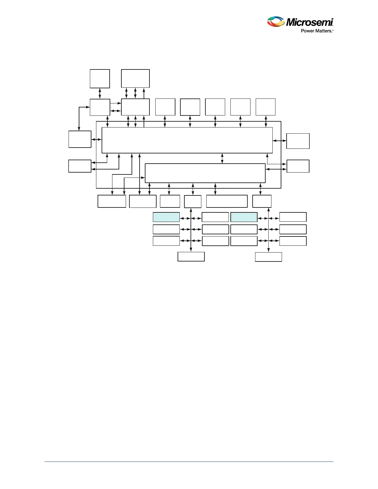
The following figure shows the MMUART peripherals within the MSS. The MMUART peripherals are
interfaced to the AHB bus matrix through APB interfaces (APB_0 and APB_1).
Figure 178 • MSS Showing MMUART Peripherals
13.2 Functional Description
This section provides the detailed description of the MMUART peripherals.
13.2.1 Architecture Overview
The functional block diagram of MMUART is shown in the following figure. The main components of
MMUART include Transmit and Receive FIFOs (TX_FIFO and RX_FIFO), baud rate generator, input
filters, LIN Header Detection and Auto Baud Rate Calculation block, RZI modulator and demodulator,
and interrupt controller.
While transmitting data, the parallel data is written to TX_FIFO of the MMUART to transmit in serial form.
While receiving data to RX_FIFO, the MMUART transforms the serial input data into parallel form to
facilitate reading by the Cortex-M3 processor.
The baud rate generator contains free running counters and utilizes the asynchronous and synchronous
baud rate generation circuits. The input filters in MMUART suppress the noise and spikes of incoming
clock signals and serial input data based on the filter length. The RZI modulation/demodulation blocks
are intended to allow for IrDA serial infrared (SIR) communications. The operational details of these sub
blocks are explained in detail in Details of Operation, page 474.
AHB Bus Matrix
eSRAM_0
System
Controller
Cache
Controller
SD IC
ARM Cortex-M3
Processor
SDI
MSS DDR
Bridge
PDMA
MS6
MM3
AHB To AHB Bridge with Address Decoder
USB OTG
HPDMA
MDDR
APB_0
SYSREG
Triple Speed
Ethernet MAC
FIC_0
MM4 MS4
MS2 MS3 MS0
MS5
MS1
MM5 MM6
MM7
MM8
MM2 MM1 MM0 MM9
IDC
D/S
eNVM_0 eNVM_1 eSRAM_1
FIC_2 (Peripheral
Initialization)
APB_1
MMUART_0
SPI_0
I2C_0
PDMA
Configuration
WATCHDOG
FIIC
TIMERx2
MMUART_1
SPI_1
I2C_1
GPIO
CAN
RTC
COMM_BLK
FIC_1
MSS_FIC
MS6_USB
MS5_MAC MS5_SR MS5_APB0 MS5_FIC2 MS5_APB1