Embedded SRAM (eSRAM) Controllers
UG0331 User Guide Revision 15.0 192
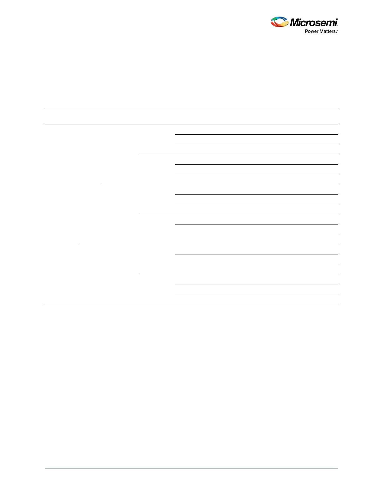
The following table describes the wait states in different operation modes. These values indicate the
number of wait states inserted by eSRAM controllers and apply to the reads and writes from masters
within the MSS. Accessing eSRAM blocks from the FPGA fabric is performed through the fabric interface
controller (FIC) interfaces. The FIC interface supports Bypass mode and Pipeline mode.
In Pipeline mode, the FIC interface adds one extra clock cycle for read and write, so the overall latency
for accessing the eSRAM increases in this case.
Table 121 • Wait States in Different Operation Modes
Pipeline eSRAM
SECDED
Mode Operation Size
Number of Wait
States
Number of Wait States
(Reads following a Write)
Enabled 32 KB
RAM
SECDED-
ON Mode
Write 32-Bit 0 1
16-Bit 1 3
8-Bit 1 3
Read 32-Bit 1 2
16-Bit 1 2
8-Bit 1 2
SECDED-
OFF Mode
Write 32-Bit 0 0
16-Bit 0 0
8-Bit 0 0
Read 32-Bit 1 2
16-Bit 1 2
8-Bit 1 2
8 KB
RAM
SECDED-
OFF Mode
Write 32-Bit 1 1
16-Bit 0 0
8-Bit 0 0
Read 32-Bit 2 3
16-Bit 1 2
8-Bit 1 2