Reset Controller
UG0331 User Guide Revision 15.0 664
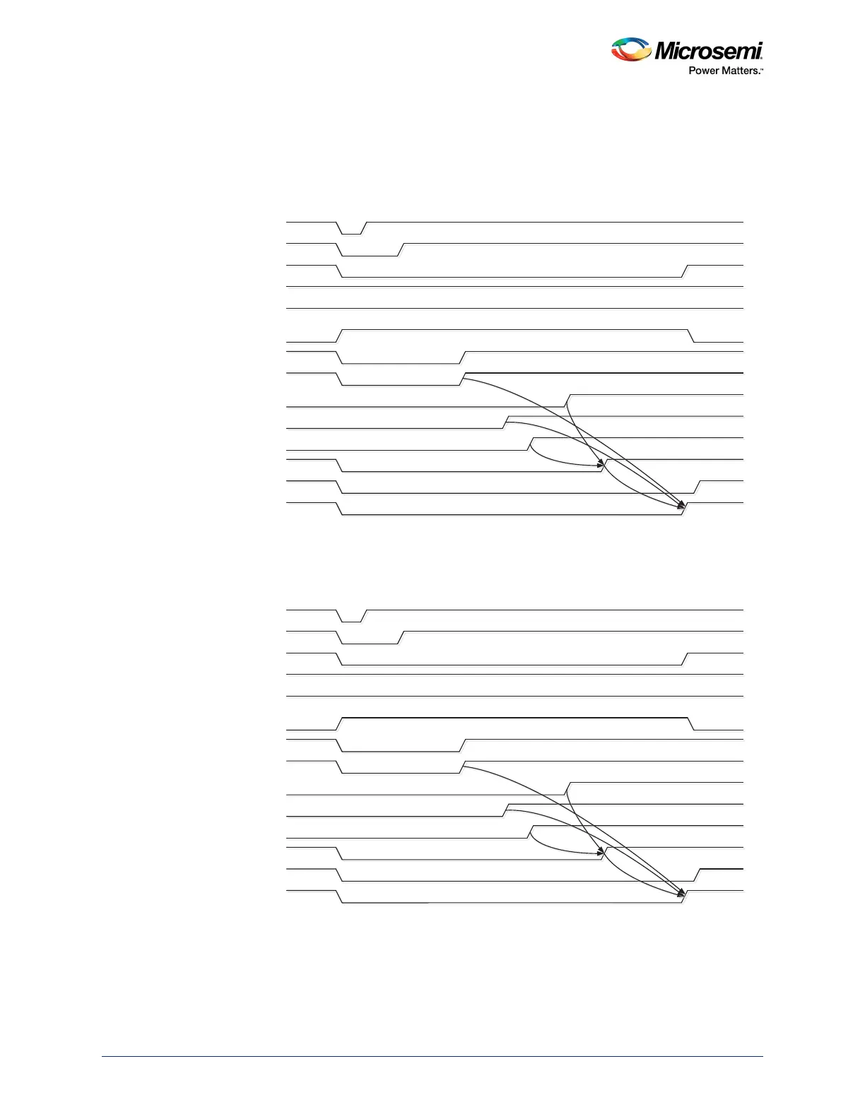
21.3.3 Timing Diagrams
The following figures show the timing of reset signals for reset sequences initiated by the assertion of
POWER_ON_RESET_N, FIC_2_APB_M_PRESET_N, EXT_RESET_IN_N, and
USER_FAB_RESET_IN_N signals.
Figure 299 • Timing for Reset Signals Initiated by the Assertion of POWER_N_RESET_N
Figure 300 • Timing for Reset Signals Initiated by the Assertion of FIC_2_APB_M_PRESET_N
32:(5B21B5(6(7B1
)$%B5(6(7B1
86(5B)$%B5(6(7B1
5(6(7B1B)0
0B5(6(7B1
(;7B5(6(7B287
0''5B''5B$;,B6B&25(B5(6(7B1
)''5B&25(B5(6(7B1
)3//B/2&.
6',)[B63//B/2&.
6',)[B3+<B5(6(7B1
6',)[B&25(B5(6(7B1
,1,7B'21(
&21),*B'21(
XV
''5
VHWWOLQJWLPH
),&BB$3%B0B35(6(7B1
)$%B5(6(7B1
86(5B)$%B5(6(7B1
5(6(7B1B)0
0B5(6(7B1
(;7B5(6(7B287
0''5B''5B$;,B6B&25(B5(6(7B1
)''5B&25(B5(6(7B1
)3//B/2&.
6',)[B63//B/2&.
6',)[B3+<B5(6(7B1
6',)[B&25(B5(6(7B1
,1,7B'21(
&21),*B'21(
XV
''5
VHWWOLQJWLPH