Cortex-M3 Processor (Reference Material)
UG0331 User Guide Revision 15.0 119
3.7.3.1 SysTick Control and Status Register
The SYST_CTRL register enables the SysTick features. See the register summary in the preceding table
for its attributes. The bit assignments are:
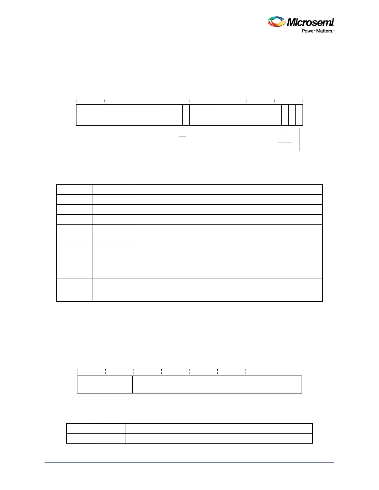
Figure 46 • SYST_CTRL Register Bit Assignments
When ENABLE is set to 1, the counter loads the RELOAD value from the SYST_RVR register and then
counts down. On reaching 0, it sets the COUNTFLAG to 1 and optionally asserts the SysTick depending
on the value of TICKINT. It then loads the RELOAD value again, and begins counting.
3.7.3.2 SysTick Reload Value Register
The SYST_RVR register specifies the start value to load into the SYST_CVR register. See the register
summary in Ta b le 71 , page 119 for its attributes. The bit assignments are:
Figure 47 • SYST_RVR Register Bit Assignments
1. SysTick calibration value.
Table 72 • SYST_CTRL Register Bit Assignments
Bits Name Function
[31:17] Reserved.
[16] COUNTFLAG Returns 1 if timer counted to 0 since last time this was read.
[15:3] Reserved.
[2] CLKSOURCE Selects the SysTick timer clock source:
1: processor clock. Determined by STCLK_DIVISOR bits in M3_CR register.
[1] TICKINT Enables SysTick exception request:
0: counting down to zero does not assert the SysTick exception request
1: counting down to zero to asserts the SysTick exception request.
Software can use COUNTFLAG to determine if SysTick has ever counted to
zero.
[0] ENABLE Enables the counter:
0: counter disabled
1: counter enabled.
Table 73 • SYST_RVR Register Bit Assignments
Bits Name Function
[31:24] Reserved.
0Reserved
31 17 16 15 3 2 1 0
Reserved 0 0
COUNTFLAG
CLKSOURCE
TICKINT
ENABLE