Inter-Integrated Circuit Peripherals
UG0331 User Guide Revision 15.0 548
15.3.2 I
2
C Use Models
The following sections describe I
2
C use models.
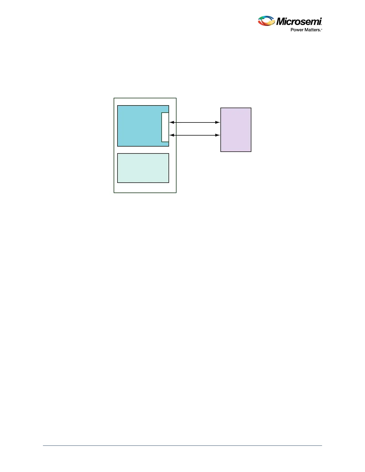
15.3.2.1 Use Model 1: Interfacing External EEPROM
The following figure shows the interfacing of the external EEPROM to I2C_0 of the SmartFusion2 MSS.
Figure 237 • Interfacing External EEPROM to MSS I2C_0 - Block Diagram
Refer to the Design Flow, page 544 to configure I2C_0 in the application. EEPROM is the target slave
device in this example.
15.3.2.1.1 Software Design Flow
I
2
C Master Mode
The I
2
C instance I2C_0 can be initialized by using MSS_I2C_init API. Refer to the
SmartFusion2_MSS_I2C_Driver_UG to use the I
2
C initialization API.
Write Operation
Write data to the target slave device using MSS_I2C_write API. This API ensures the presence of I2C_0
in Master mode for write transactions. The following parameters are required to use the I
2
C write API:
• Target slave device address (Ex.EEPROM)
• Data which is to be written to the target device
• Data size in bytes
Read Operation
Read data from the target slave device using MSS_I2C_read API. This API ensures the presence of
I2C_0 in Master mode for read transactions. The following parameters are required to use the I
2
C read
API:
• Target slave device address (Ex.EEPROM)
• Data buffer to collect the data from the target device
• Data size in bytes
For any I
2
C read or write transaction to complete, MSS_I2C_wait_complete API should be called. This
API waits for the current I
2
C transaction to complete.
SCL
SDA
External EEPROM
SmartFusion2
I2C _ 0
I2C_0_SCL
I2C_0_SDA
MSS
FABRIC