RTC System
UG0331 User Guide Revision 15.0 609
18.4.1 Counter Bit Positions
The RTC counters support the following two counting modes:
• Binary Mode: In Binary mode a 43-bit counter is provided.
• Calendar Mode: The 43 bits are allocated as following:
• Weekday, 1: Sunday, 2: Monday …. 7:Saturday
• Reset date is Saturday 1 January 2000.
• The leap year calculations assume the year value where 0-255 is mapped to 2000 to 2255.
18.4.2 Register Bit Allocation
Depending on the CLOCK_MODE setting, the bit mapping is given in Tab le 60 5, page 609.
The following table shows the Register Map for RTC.
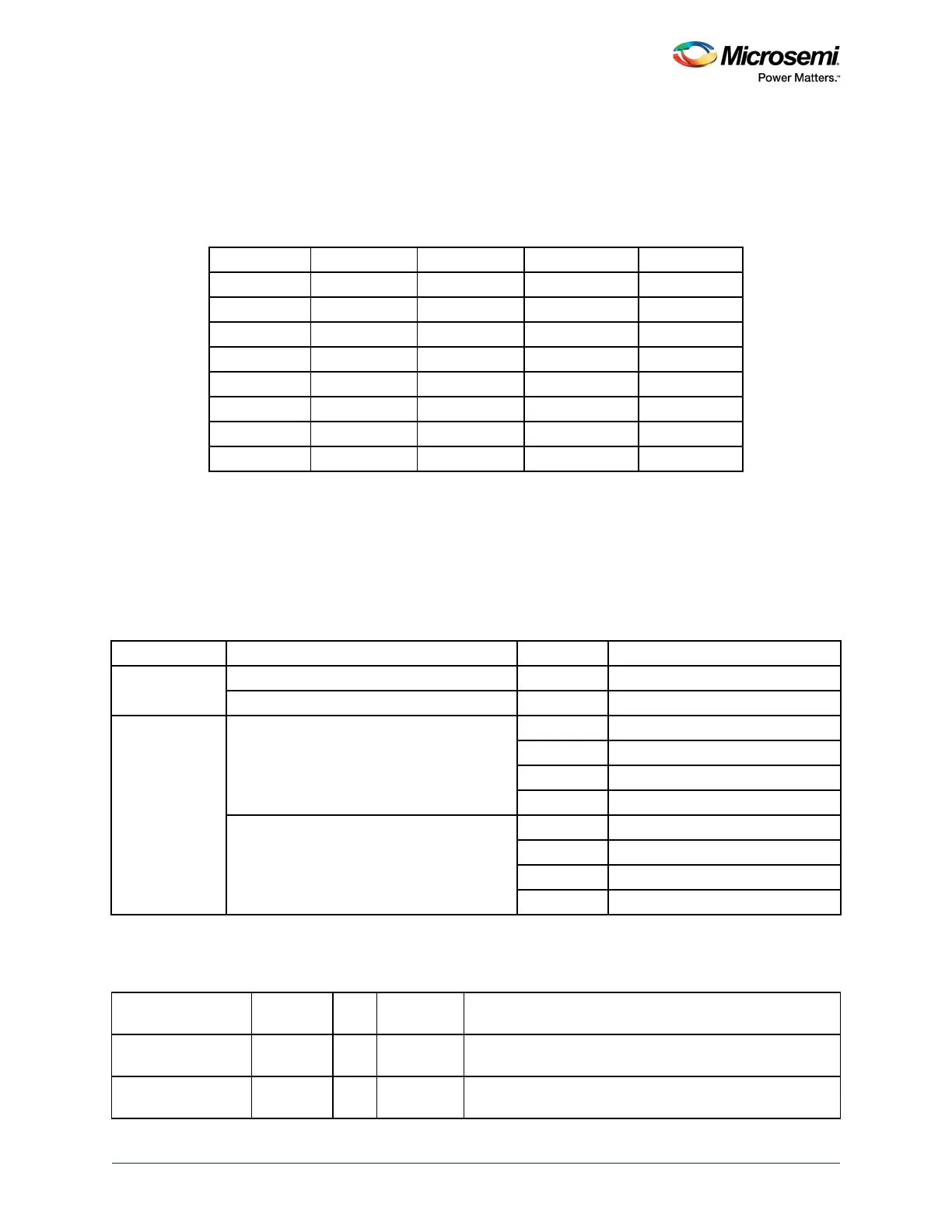
Table 604 • Allocation of Bits in Calendar Mode
Counter Counts Size Bits Bits in Counter Reset Value
Seconds 0-59 6 [5:0] 0
Minutes 0-59 6 [11:6] 0
Hours 0-23 5 [16:12] 0
Day 1-31 5 [21:17] 1
Month 1-12 5 [25:22] 1
Year 0-255 8 [33:26] 0
Weekday 1-7 3 [36:34] 7
Week 1-52 6 [42:37] 1
Table 605 • Register Bit Allocation
Clock Mode Date Time Alarm Compare Register Bits Description
0 Lower [31:0] Binary Count[31:0]
Upper [10:0] Binary Count[42:32]
1 Lower [7:0] Seconds
[15:8] Minutes
[23:16] Hours
[31:24] Day
Upper [7:0] Month
[15:8] Year
[23:16] Weekday
[29:24] Week
Table 606 • Register Map for RTC
Register Name
Address
Offset R/W Reset Value Description
Control 0x00 R/W 0 The control register is an 11-bit register that defines the
operations of the RTC.
Mode 0x04 R/W 0 This register should only be written when the RTC is
stopped
—when the control register bit 0 reads as a '0'.