RTC System
UG0331 User Guide Revision 15.0 611
18.4.4 Mode Register
This register should only be written when the RTC is stopped— when the control register bit 0 reads as a
'0’.
18.4.5 Prescaler
This register should only be written when the RTC is stopped— when the control register bit 0 reads as a
'0'.
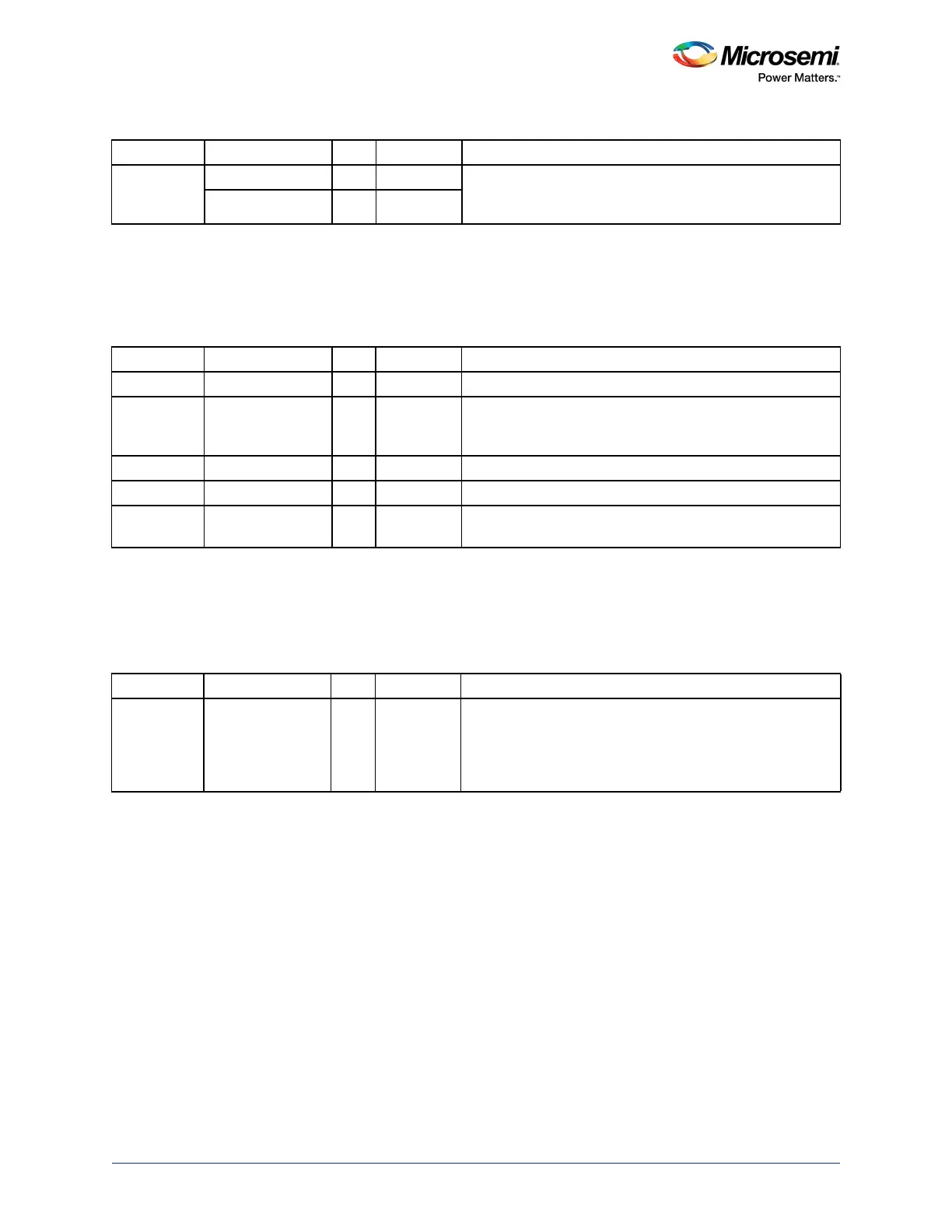
0 Start W 0 When '1' is written, the RTC starts.
When it is read, it indicates that the RTC is running.
It reads back '1' as soon as the start bit is written.
Running R 0
Table 608 • Mode
Bit Number Name R/W Reset Value Description
4 Wake_reset_ps R/W 0 When a wakeup occurs, resets the Prescaler.
3 Wake_continue R/W 0 When a wakeup occurs, continues counting; otherwise the
counters, including the Prescaler, stop until wake-up is
cleared.
2 Wake_reset R/W 0 When a wake-up occurs, resets the RTC.
1 Wake_enable R/W 0 Enables the wakeup (interrupt) output.
0 Clock_mode R/W 0 0: Binary counter
1: Calendar mode
Table 609 • Prescaler
Bit Number Name R/W Reset Value Description
[25:0] Prescaler R/W 0 The value by which the incoming clock is divided is set in the
Prescaler. It should be set so as to achieve 1 Hz from the
incoming RTC clock.
Value: Clock Frequency – 1
Value must be greater than 1.
Table 607 • Control (continued)
Bit Number Name R/W Reset Value Description