Serial Peripheral Interface Controller
UG0331 User Guide Revision 15.0 525
14.3.2 SPI Use Models
14.3.2.1 Use Model 1: Accessing the External SPI Flash Using MSS SPI_0
The external SPI flash can be interfaced to either the MSS SPI_0 or SPI_1 peripherals of the
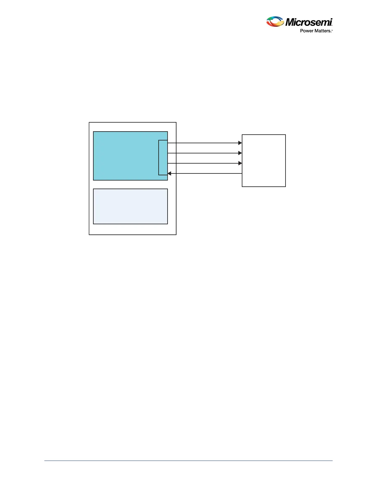
SmartFusion2 MSS. In this example, the external SPI flash is interfaced to MSS SPI_0. The MSS SPI_0
is configured as a master with the slave select line connected to the chip select of the external SPI Flash.
The following figure shows interfacing the external SPI flash to MSS SPI_0.
Figure 226 • Interfacing External SPI Flash to MSS SPI_0-Block Diagram
Follow the instructions provided in the Design Flow, page 520 to configure SPI_0 in the application. The
external SPI flash is the target SPI slave device in this example.
SPI_0_DO
SPI_0_CLK
SPI_0_SSO
SPI_0_DI
SI
SCK
CS
SO
MSS
FPGA Fabric
SPI_0
External Flash Memory
SmartFusion 2