Universal Serial Bus OTG Controller
UG0331 User Guide Revision 15.0 289
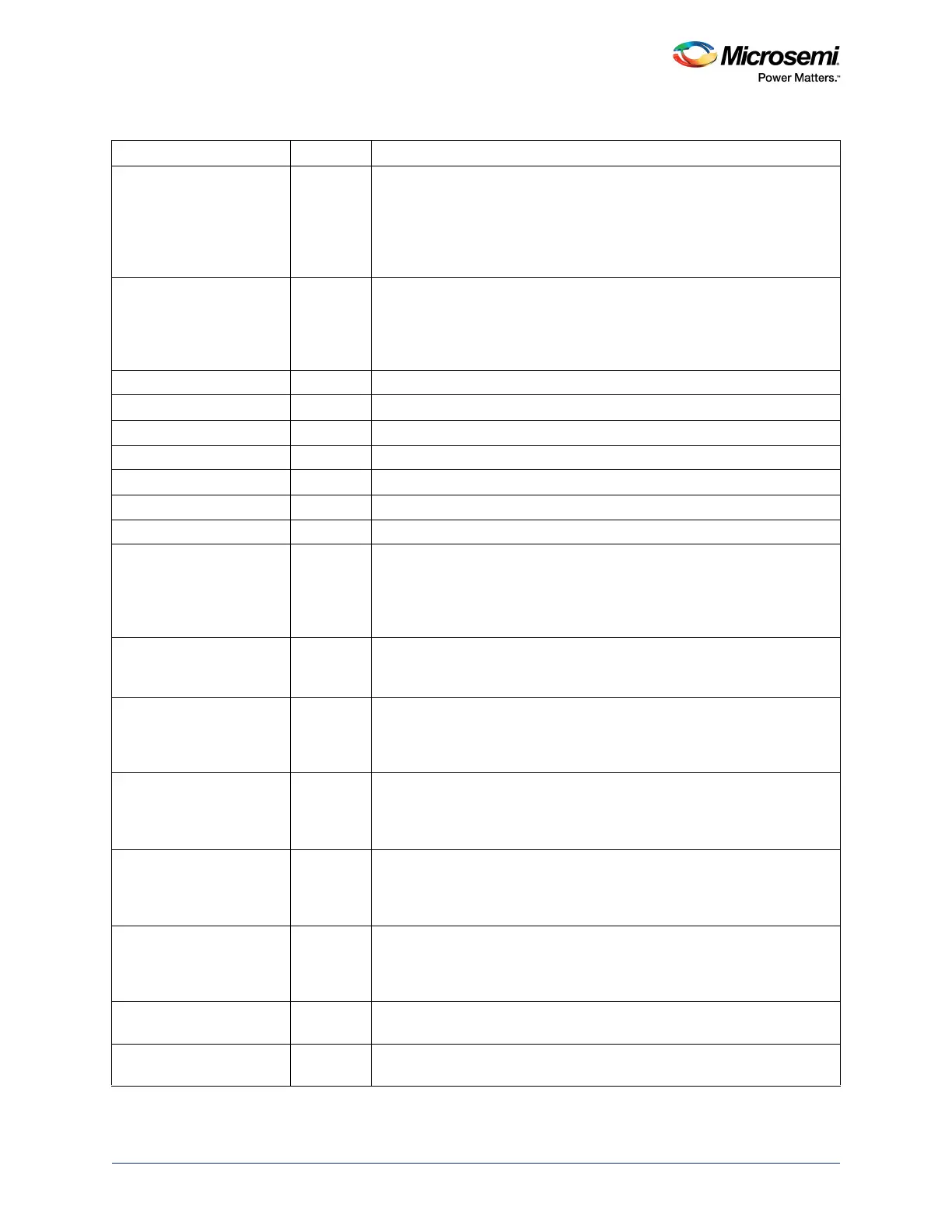
UTMI_LINESTATE[1:0] In Shows the current state of single-ended receivers. LINESTATE[0] reflects
the state of D+; LINESTATE[1] reflects state of D-.
00: SE0
01: J State
10: K State
11: SE1
UTMI_OPMODE[1:0] Out Selects Operating mode
00: Normal operation
01: Non-driving
10: Bit stuffing and NRZI encoding disabled
11: Reserved
UTMI_XDATAIN[7:0] In Received data
UTMI_XDATAOUT[7:0] Out Data to be transmitted
UTMI_TXVALID Out Transmit data valid. Indicates that valid data has been transmitted.
UTMI_TXREADY In Transmit data ready. Indicates that the transmitter requires data.
UTMI_RXVALID In Receive data valid. Indicates that valid data has been received.
UTMI_RXACTIVE In Indicates that a valid packet is being received.
UTMI_RXERROR In Indicates that the received packet is about to be aborted due to an error.
UTMI_XCVRSEL[1:0] Out Transceiver select
00: HS transceiver
01: FS transceiver
10: LS transceiver
11: FS transceiver, LS packet
UTMI_TERMSEL Out Termination select. When 0, high speed termination is enabled; when 1, full
speed termination is enabled.
May be used to switch the pull-up resistor on D+
UTMI_VBUSVALID In Compares VBus to selected VBus valid threshold (required to be between
4.4 V and 4.75 V)
1: Above the VBus valid threshold
0: Below the VBus valid threshold
UTMI_AVALID In Compares VBus to session valid threshold for a B device (required to be
between 0.8 V and 2 V)
1: Above the session valid threshold
0: Below the session valid threshold
UTMI_SESSEND In Compares VBus to session end threshold (required to be between 0.2 V
and 0.8 V)
0: Above the session end threshold
1: Below the session end threshold
UTMI_SESSEND In Compares VBus to session end threshold (required to be between 0.2 V
and 0.8 V)
0: Above the session end threshold
1: Below the session end threshold
UTMI_DRVVBUS Out Enables VBus power (used when the USB controller operates as an A
device)
UTMI_CHRGVBUS Out Charges VBus (used during session request when the USB controller
operates as a B device)
Table 192 • UTMI+Interface Signals at Fabric Interface in SmartFusion2 Device (continued)
Signal Name Direction Description