MMUART Peripherals
UG0331 User Guide Revision 15.0 472
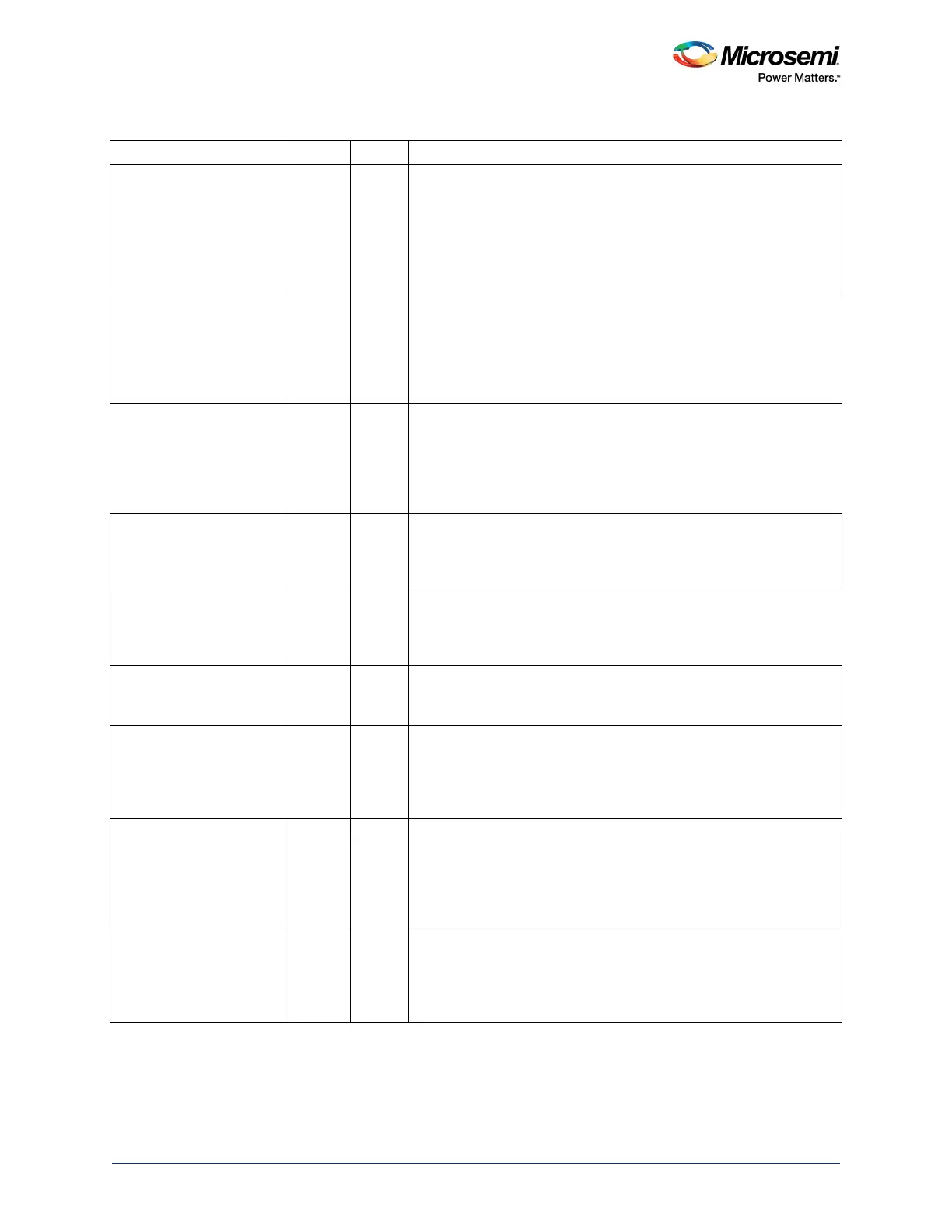
MMUART_X_RI Input Low Ring indicator.
This signal is used in the modem interface. The active Low signal is
an input showing when the attached device (modem) senses a ring
signal on the telephone line. MMUART passes this information to the
Cortex-M3 processor through the MSR. This register also gives an
indication when the RI trailing edge is sensed. This signal can either
go to the fabric or to the I/O pad.
MMUART_X_RTS Output Low Request to send.
This signal is used in the modem interface. The active Low output
signal is used to inform the attached device (modem) that MMUART
is ready to send data. It is programmed by the Cortex-M3 processor
through the MCR. This signal can either go to the fabric or to the I/O
pad.
MMUART_X_DTR Output Low Data terminal ready.
This signal is used in the modem interface. The active Low output
signal informs the attached device (modem) that MMUART is ready
to establish a communications link. It is programmed by the Cortex-
M3 processor through the MCR. This signal can either go to the fabric
or to the I/O pad.
MMUART_X_RXD Input Serial input data
This is the data transmitted into MMUART. It is synchronized with the
APB clock (master clock) input pin. This signal can either go to the
fabric or to the I/O pad.
MMUART_X_TXD Output Serial output data.
This is the data transmitted from MMUART. It is synchronized with the
BAUDOUT output pin. This signal can either go to the fabric or to the
I/O pad.
MMUART_X_SCK_IN Input Serial input synchronous clock. The MMUART_X_SCK can be
configured as an input synchronous clock from master when the
MMUART_X acts as a slave.
MMUART_X_SCK_OUT /
BAUDOUTN
Output Low In Synchronous mode, it is the serial output clock, SCK_OUT.
MMUART_X_SCK can be configured as output synchronous clock to
a slave when MMUART_X acts as a master.
In Asynchronous mode, it is the baud rate clock derived from
APB_X_CLK and BAUDOUTN.
MMUART_X_ESWM Output High Single-wire, half-duplex enable.
If this signal is active High, then the data I/O is configured for half-
duplex operation over a single-wire, using the Tx pad (out signal). If
Low, then the data I/O has separate Tx (out) and Rx (in) pins. Single-
wire mode enable (ESWM) signal goes to the FPGA fabric, when it
can be used on any pad.
MMUART_X_TE Output High Transmitter output enable.
This active High signal is used as a bi-directional enable for single-
wire half-duplex operation. An active High signal transmits out, and a
Low signal is received. TE usage implies that the MMUART is
configured in single-wire mode with the single-wire mode (SWM) bit.
Table 464 • MMUART I/O Signal Descriptions (continued)
Name Type Polarity Description