Universal Serial Bus OTG Controller
UG0331 User Guide Revision 15.0 371
10.3.15.2 USB_IO_INPUT_SEL_CR Register Bit Definitions
10.3.15.3 USB_CR Register Bit Definitions
10.3.15.4 USB_EDAC_CNT Register Bit Definitions
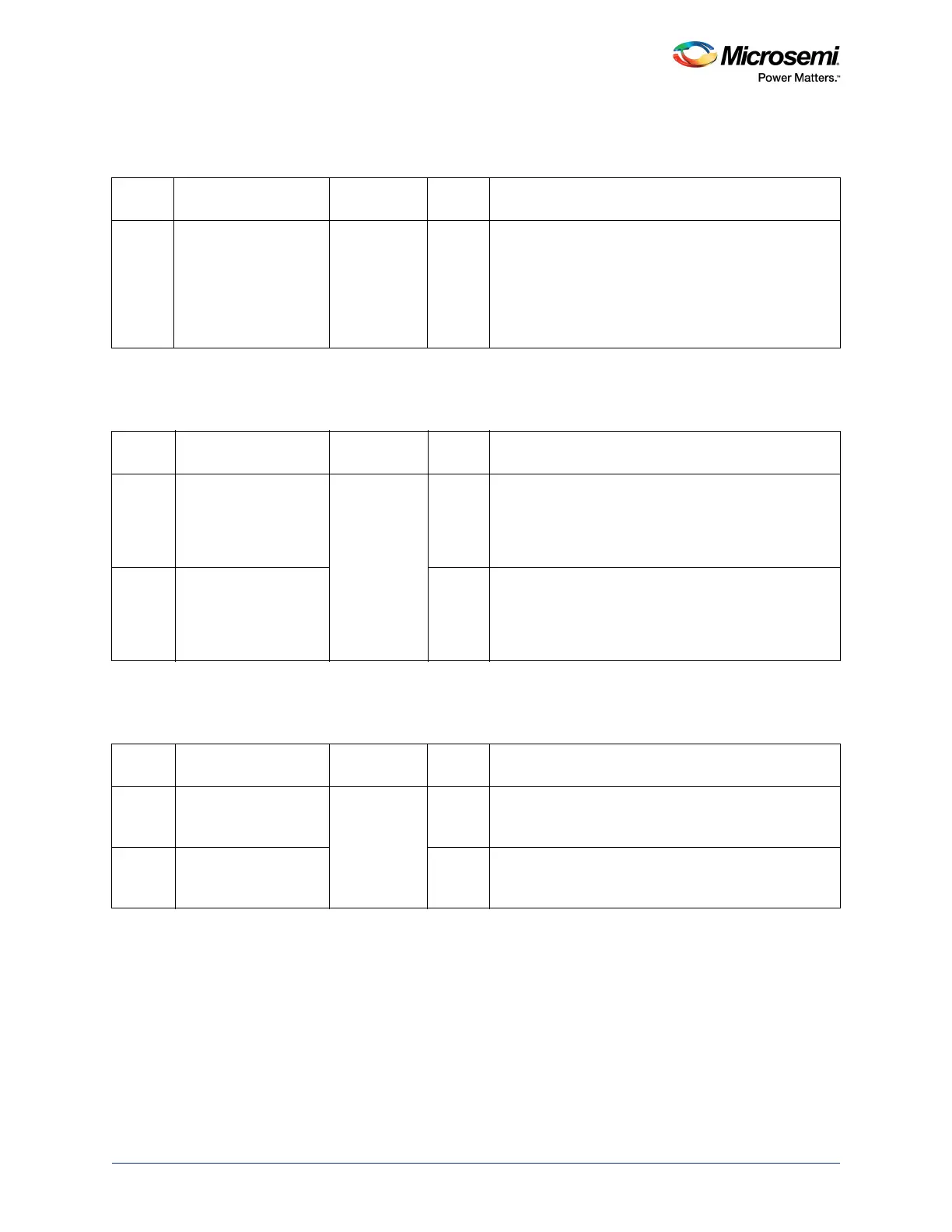
Table 313 • USB_IO_INPUT_SEL_CR
Bit
Number Name Address
Reset
Value Function
2 USB_IO_INPUT_SEL 0x40038064 0 Selects one of the four USB data interfaces from
IOMUXCELLs and I/O pads. Following are the allowed
values:
00: USBA interface can be connected to USB controller
01: USBB interface can be connected to USB controller
10: USBC interface can be connected to USB controller
11: USBD interface can be connected to USB controller
Table 314 • USB_CR
Bit
Number Name Address
Reset
Value Function
0 USB_UTMI_SEL 0x4003807C 0 This signal is used to configure USB controller interface
as ULPI PHY or UTMI interface. Following are the
allowed values:
0: ULPI PHY Interface is selected
1: UTMI Interface is selected
1 USB_DDR_SELECT 0 This signal is used to configure whether the USB
controller works in Single Data Rate (SDR) mode or
Double Data Rate (DDR) mode. Allowed values:
0: SDR mode is selected
1: DDR mode is selected
Table 315 • USB_EDAC_CNT
Bit
Number Name Address
Reset
Value Function
[15:0] USB_EDAC_CNT_1E 0x40038104 0 This is a 16-bit counter value in USB incremented by
USB EDAC 1-bit errors. The counter does not roll back
and stays at its maximum value, if reached.
[31:16] USB_EDAC_CNT_2E 0 This is a 16-bit counter value in USB incremented by
USB EDAC 2-bit errors. The counter does not roll back
and stays at its maximum value, if reached.