3 Spectrum Analyzer Mode
3.5 ACP Measurement
–
BOTH - Both sides in the sub-block gap are enabled
–
POSitive - The lower side in the sub-block gap only (that is, positive sideband
of the lower sub-block) is enabled
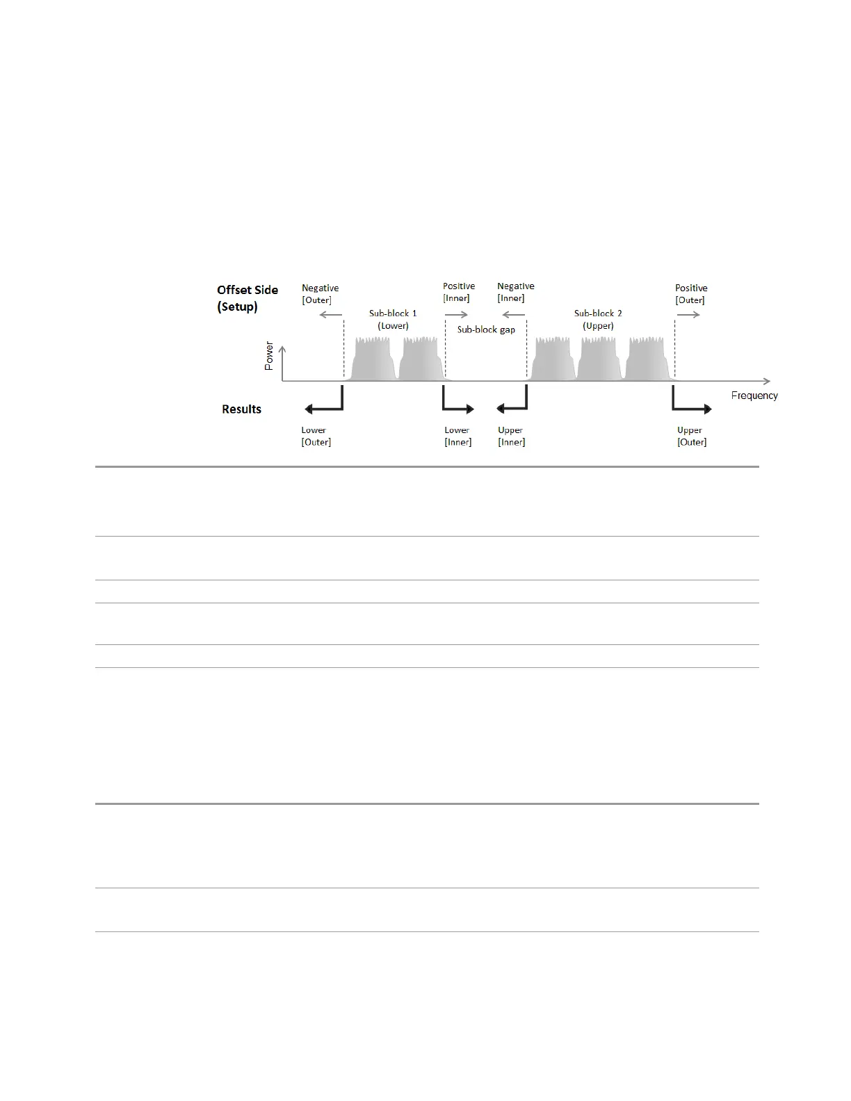
The diagram below shows the relation between the negative/positive offset side
setups and the upper/lower results in the MSR, LTEAFDD and LTEATDD Modes.
Remote
Command
[:SENSe]:ACPower:OFFSet[1]|2:INNer:LIST:SIDE NEGative | BOTH | POSitive, …
[:SENSe]:ACPower:OFFSet[1]|2:INNer:LIST:SIDE?
Subopcode: 1 = BTS/Downlink (Default), 2 = MS/Uplink
Example
:ACP:OFFS:INN:LIST:SIDE BOTH
:ACP:OFFS:INN:LIST:SIDE?
Notes If you set POS or NEG in an offset, result of the inactive side returns -999
Preset When "Max Num of Offsets" on page 1010 is 12, the preset value of Offset G ~ L is BOTH
BOTH, BOTH, BOTH, BOTH, BOTH, BOTH | BOTH, BOTH, BOTH, BOTH, BOTH, BOTH
State Saved Saved in instrument state
Range
NEGative|BOTH|POSitive
Method
Lets you turn RRC filtering of each offset on or off. The value (roll off) for the filter is
set to the value of the Filter Alpha parameter.
Remote
Command
[:SENSe]:ACPower:OFFSet[1]|2:INNer:LIST:FILTer[:RRC][:STATe] ON | OFF | 1 |
0,…
[:SENSe]:ACPower:OFFSet[1]|2:INNer:LIST:FILTer[:RRC][:STATe]?
Subopcode: 1 = BTS/Downlink (Default), 2 = MS/Uplink
Example
:ACP:OFFS:INN:LIST:FILT 1,0,0
:ACP:OFFS:INN:LIST:FILT?
Notes 1|ON = RRC Weighted, 0|OFF = Integ BW
Spectrum Analyzer Mode User's &Programmer's Reference 1001

 Loading...


