6 Input/Output
6.5 Corrections
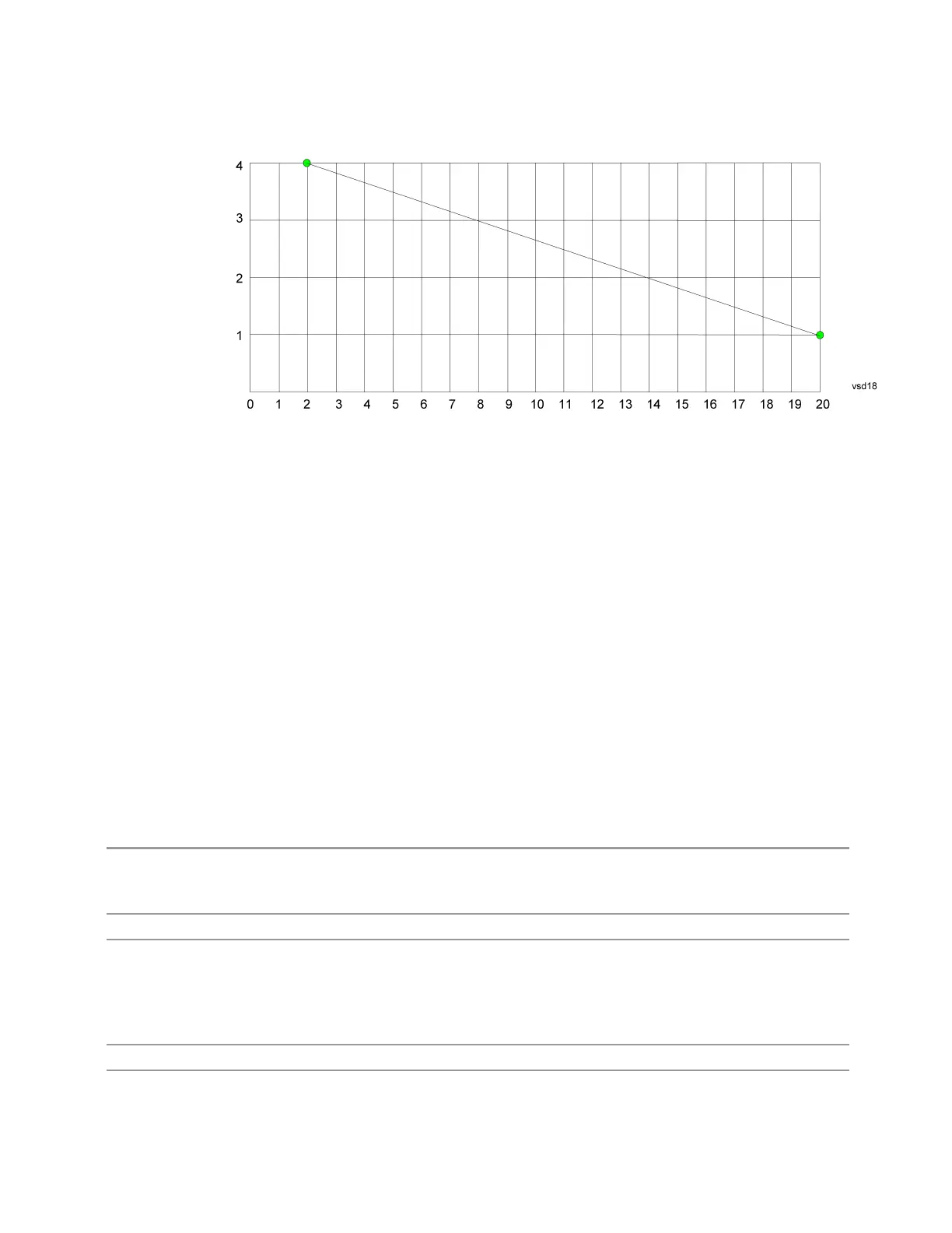
The correction to be used for each bucket is taken from the interpolated correction
curve at the center of the bucket.
6.5.6.3 Transducer Unit
For devices (like antennas) that make measurements of field strength or flux density,
the correction array should contain within its values the appropriate conversion
factors such that, when the data on the instrument is presented in dBµV, the display
is calibrated in the appropriate units. The "Transducer Unit" used for the conversion
is contained within the corrections array database. It may be specifiedor loaded in
from an external file or SCPI.
When an array with a Transducer Unit other than "None" is turned on, the Y Axis
Unit of the instrument is forced to that unit. When this array is turned on, and it
contains a Transducer Unit other than “None”, the Y Axis Unit of the instrument is
forced to that Transducer Unit., and all other Y Axis Unit choices are grayed out.
Transducer Unit only appears in certain Modes, it does not appear in all Modes that
support Corrections.
See "Examples" on page 2430
Remote Command
[:SENSe]:CORRection:CSET[1]|2|…|16:ANTenna[:UNIT] GAUSs | PTESla | UVM |
UAM | UA | NOConversion
[:SENSe]:CORRection:CSET[1]|2|…|16:ANTenna[:UNIT]?
Example
:CORR:CSET:ANT GAUS
Dependencies Only one Transducer units can be on at any given time. Note that this means that if a correction file
with a Transducer Unit is loaded into a particular Correction, all other Corrections are set to that same
Transducer unit
When Normalize is On (in the Trace, Normalize menu) Transducer Unit is grayed-out and forced to
None
Preset Unaffected by Preset. Set to NOC by Restore Input/Output Defaults
State Saved Saved in instrument state
Spectrum Analyzer Mode User's &Programmer's Reference 2429

 Loading...


