ADSP-21368 SHARC Processor Hardware Reference 3-81
External Port
The
ID2-0 pins provide a unique identity for each processor in a multipro-
cessing system. The first processor should be assigned ID = 001, the second
should be assigned ID = 010, and so on. One of the processors must be
assigned ID = 001 in order for the bus synchronization scheme to function
properly.
L
The processor with ID = 001 holds the external bus control lines
stable (pull-up enabled) during reset.
A processor in a shared memory system can determine which processor is
the current bus master by reading the
CRBM2-0 bits of the SYSTAT register
(see “System Status Register (SYSTAT)” on page A-9). These bits provide
the values of the ID2-0 inputs of the current bus master.
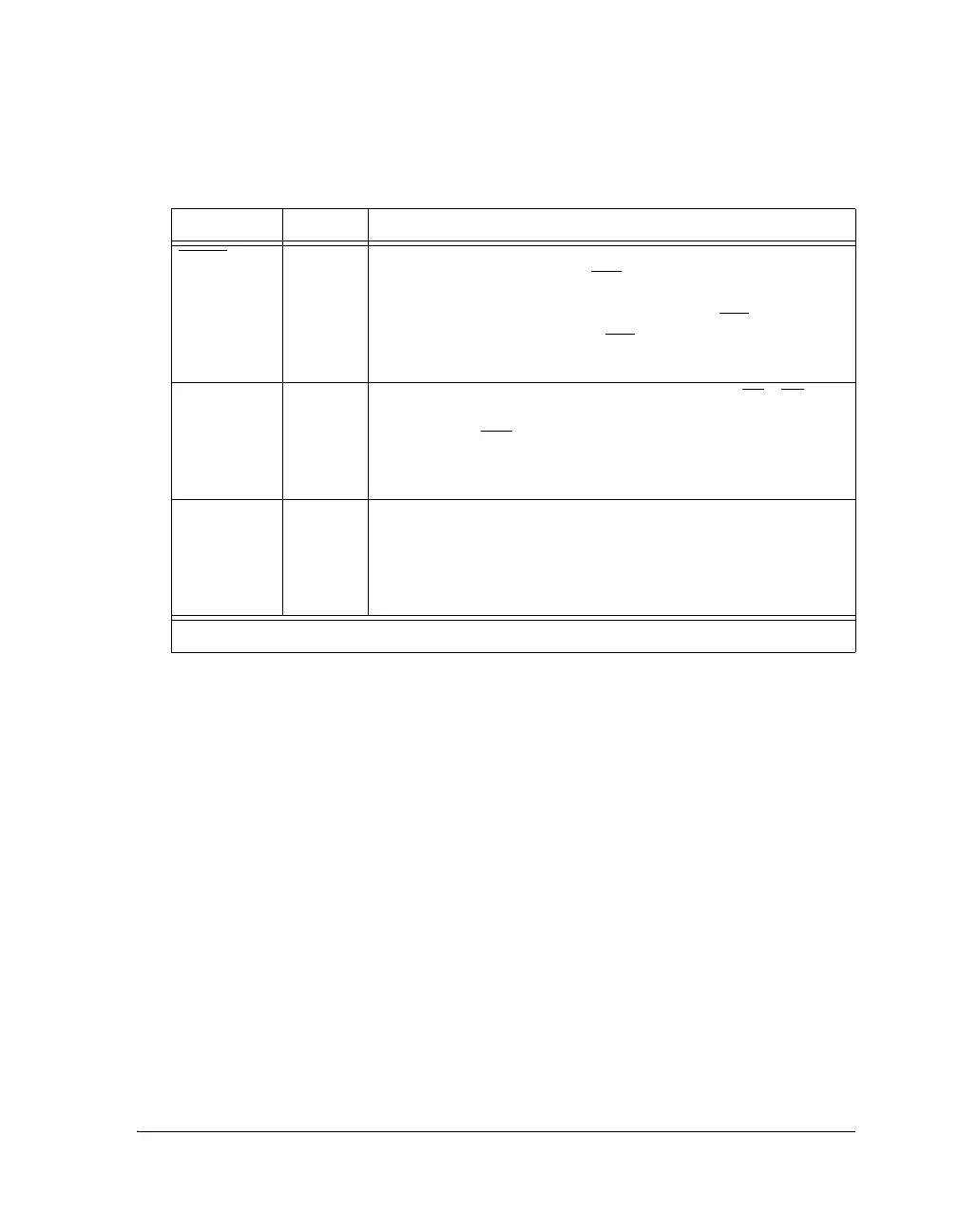
Table 3-30. Shared Memory Pins
Signal Type Definition
BR4–1 I/O/S Shared Memory Bus Requests. Used to arbitrate for bus mastership.
A processor only drives its own BRx line (corresponding to the value
of its ID2-0 inputs) and monitors all others. In a shared memory
system with less than four processors, the unused BRx
pins should
be tied high; the processor’s own BRx line must not be tied high or
low because it is an output.
ID2–0 I Shared Memory ID. Determines which bus request (BR1–BR4) is
used by the ADSP-21368. ID = 001 corresponds to BR1, ID = 010
corresponds to BR2
, and so on. Use ID = 000 or ID = 001 in single
processor systems. These lines are a system configuration selection
that should be hardwired or only changed at reset.
RPBA I Rotating Priority Bus Arbitration Select. When RPBA is high,
rotating priority for shared memory bus arbitration is selected.
When RPBA is low, fixed priority is selected. This signal is a system
configuration selection which must be set to the same value on every
processor.
I = Input, S = Synchronous, O = Output
 Loading...


