ADSP-21368 SHARC Processor Hardware Reference A-123
Register Reference
Interrupt Enable Registers (UARTxIER)
The UART interrupt enable registers (UARTxIER) are used to enable
requests for system handling of empty or full states of UART data regis-
ters. Unless polling is used as a means of action, the UARTRBFIE and/or
UARTTBEIE bits in these registers are normally set.
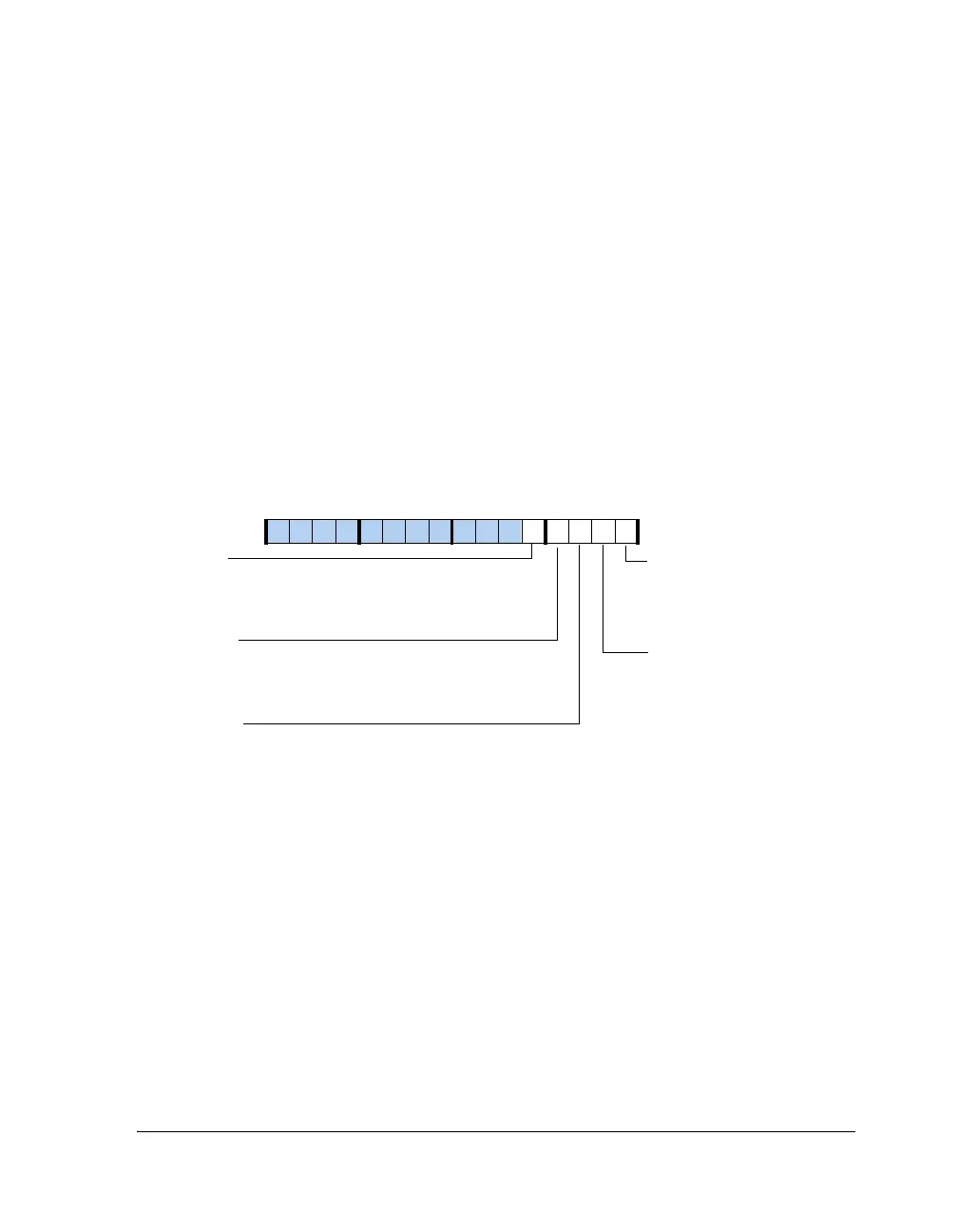
The UARTxIER register (shown in Figure A-52) is mapped to the same
address as the UARTxDLH register. To access the UARTxIER register, the
UARTDLAB bit in the UARTxLCR register must be cleared.
Figure A-52. UART Interrupt Enable Register
15 14 13 12 11 10 9 8 7 6 5 4 3 2 1 0
0000000000000000
UARTRBFIE
UARTTBEIE
Enable Receive Buffer Full
Interrupt
0=No interrupt
1=Generate RX interrupt if DR bit
in UART_LSR is set
Enable Transmit Buffer Empty
Interrupt
0=No interrupt
1=Generate TX interrupt if THRE
bit in UART_LSR is set
UART0IER (0x3C01)
UART1IER (0x4001)
UARTLSIE
Enable RX Status Interrupt
0=No interrupt
1=Generate line status interrupt if any
of UART_LSR[4–1] is set
UARTTXFIE
Enable Transmit Complete Interrupt
0=No interrupt
1=Generate TX interrupt if TEMT bit
in UART_LSR is set
UARTADIE
Enable Address Detect Interrupt in 9-Bit Mode
0=No interrupt
1=Generate RX interrupt when address is
detected in 9-bit mode
 Loading...


