Input Data Port Registers
A-70 ADSP-21368 SHARC Processor Hardware Reference
Input Data Port DMA Control Registers
Each of the eight DMA channels have an I-register with an index pointer
(19 bits), an M-register with a modifier/stride (6 bits), and a C-register
with a count (16 bits). For example, IDP_DMA_I0, IDP_DMA_M0 and
IDP_DMA_C0 control the DMA for IDP channel 0. The following sections
describe these registers.
IDP_DMA_Ix
Table A-19 provides information about the IDP DMA index registers.
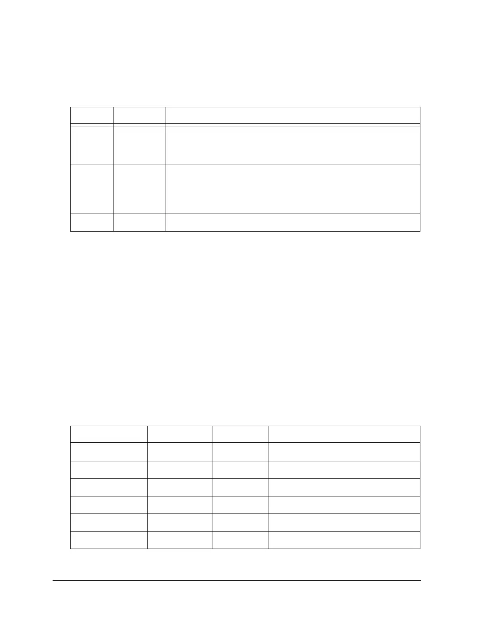
Table A-18. IDP_FIFO Register Bit Descriptions
Bit Name Description
2–0 IDP Channel Encoding. These bits indicate the serial input port
channel number that provided this serial input data.
Note: This information is not valid when data comes from the PDAP.
3LR_STATLeft/Right Channel Status. Indicates whether the data in bits 31-4 is
the left or the right audio channel as dictated by the frame sync sig-
nal. The polarity of the encoding depends on the serial mode selected
in IDP_SMODE for that channel. See Table A-16 on page A-67.
31–4 Input Data (Serial). Some LSBs can be zero, depending on the mode.
Table A-19. IDP_DMA_Ix Registers
Register Address Reset State Description
IDP_DMA_I0 0x2400 0x00000 IDP channel 0 DMA index register
IDP_DMA_I1 0x2401 0x00000 IDP channel 1 DMA index register
IDP_DMA_I2 0x2402 0x00000 IDP channel 2 DMA index register
IDP_DMA_I3 0x2403 0x00000 IDP channel 3 DMA index register
IDP_DMA_I4 0x2404 0x00000 IDP channel 4 DMA index register
IDP_DMA_I5 0x2405 0x00000 IDP channel 5 DMA index register
 Loading...


