UART DMA
2-44 ADSP-21368 SHARC Processor Hardware Reference
UART DMA
In the UART, separate receive and transmit DMA channels move data
between the UART and memory. The software does not have to move
data, it just has to set up the appropriate transfers either through the
descriptor mechanism or through auto buffer mode. See also “DMA Con-
troller Operation” on page 2-13.
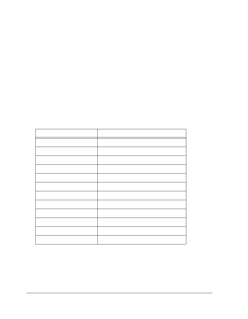
To perform DMA transfers, the UART has a special set of receive and
transmit registers. These registers are listed in Table 2-14.
No additional buffering is provided in the UART DMA channel, so the
latency requirements are the same as in non-DMA mode. However, the
latency is determined by the bus activity and arbitration mechanism and
not by the processor loading and interrupt priorities.
Table 2-13. UART DMA Registers
Register Description
UARTxRXCTL (3 bits) DMA Config/Control register for UART Rx
IIUARTxRX (19 bits) Address for DMA
IMUARTxRX (16 bits) Modifier
CUARTxRX (16 bits) Count
CPUARTxRX (20 bits) Chain Pointer
UARTxRXSTAT (3 bits) DMA Status register
UARTxTXCTL (3 bits) DMA Config/Control register for UART Tx
IIUARTxTX (19 bits) Address for DMA
IMUARTxTX (16 bits) Modifier
CUARTxTX (16 bits) Count
CPUARTxTX (20 bits) Chain Pointer
UARTxTXSTAT (3 bits) DMA Status register
 Loading...


