SRC Operation
10-18 ADSP-21368 SHARC Processor Hardware Reference
Bypass Mode
When the
BYPASS bit is set (=1), the input data bypasses the sample rate
converter and is sent directly to the serial output port. Dithering of the
output data when the word length is set to less than 24 bits is disabled.
This mode is ideal when the input and output sample rates are the same
and the LRCLK_I and LRCLK_O signals are synchronous with respect to each
other. This mode can also be used for passing through non-audio data
since no processing is performed on the input data in this mode.
De-Emphasis Filter
As discussed, the serial input port generates a frame synchronization sig-
nal, UN_f
S_IN
, that derives its clock from the positive edge of the PCLK
signal. The UN_f
S_IN
signal asserts when a new frame of left and right
data is available for the de-emphasis filter and the SRC. The de-emphasis
filter is used to de-emphasize audio data that has been emphasized. The
type of de-emphasis filter is selected by the
SRCn_DEEMPHASIS1–0 bits and
is based on the input sample rate as follows:
• 00 – No de-emphasis, audio data is passed directly to the SRC
• 01 – 32 kHz sample rate de-emphasis filter
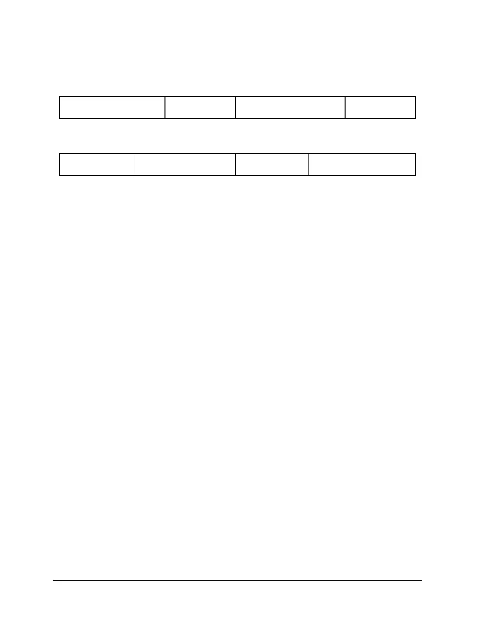
Figure 10-9. Matched-Phase Data Transmission
AUDIO DATA RIGHT
CHANNEL, 16 BITS - 24 BITS
MATCHED-PHASE
DATA, 8 BITS
MATCHED-PHASE
DATA, 8 BITS
AUDIO DATA LEFT
CHANNEL, 16 BITS - 24 BITS
Left-Justified, I
2
S, and TDM Mode
Right-Justified Mode
AUDIO DATA LEFT CHANNEL,
MATCHED-PHASE
DATA, 8 BITS
AUDIO DATA RIGHT
24 BITS
CHANNEL, 24 BITS
MATCHED-PHASE
DATA, 8 BITS
 Loading...


