ADSP-21368 SHARC Processor Hardware Reference 10-17
Asynchronous Sample Rate Converter
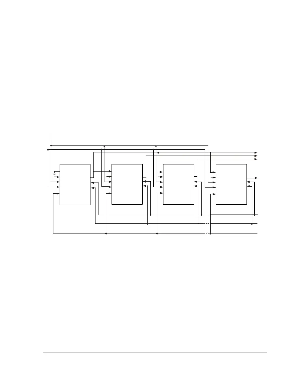
in Figure 10-8. The master device can have both its serial ports in slave
mode as depicted, or either one in master mode. The slave SRCs must
have their
MATASE_2 bits set to 1, respectively. The LRCLK_I and LRCLK_O
signals may be asynchronous with respect to each other in this mode.
There must be 32 SCLK_O cycles per subframe in matched-phase mode.
The SRC supports the matched-phase mode for all serial output data for-
mats: left-justified, I
2
S, right-justified, and TDM mode.
Note that in the left-justified, I
2
S, and TDM modes, the lower eight bits
of each channel subframe are used to transmit the matched-phase data. In
right-justified mode, the upper eight bits are used to transmit the
matched-phase data. This is shown in Figure 10-9.
Figure 10-8. Typical Configuration for Matched-Phase Mode Operation
SRCx
SLAVE1
SDATA_O
SRCx
PHASE-MASTER
SRCx
SLAVE2
SRCX
SLAVEn
LRCLKI (FS_IN)
SCLKI
LRCLKO
(FS_OUT)
SCLKO
(64FS_OUT)
RESET
SDOM
SDO1
SDO2
SDON
TDM_IN
SDATA_I
LRCLK_I
SCLK_I
RESET
SCLK_O
LR C LK_ O
SDATA_O
TDM_IN
SDAT A_ I
LRCLK_I
SCLK_I
RESET
SCLK_O
LRCLK_O
SDATA_O
TDM_IN
SDATA_I
LRCLK_I
SCLK_I
RESET
SCLK_O
LRCLK_O
SDATA_O
TDM_IN
SDATA_I
LRCLK_I
SCLK_I
RESET
SCLK_O
LRCLK_O
 Loading...


