Serial Peripheral Interface Registers
A-58 ADSP-21368 SHARC Processor Hardware Reference
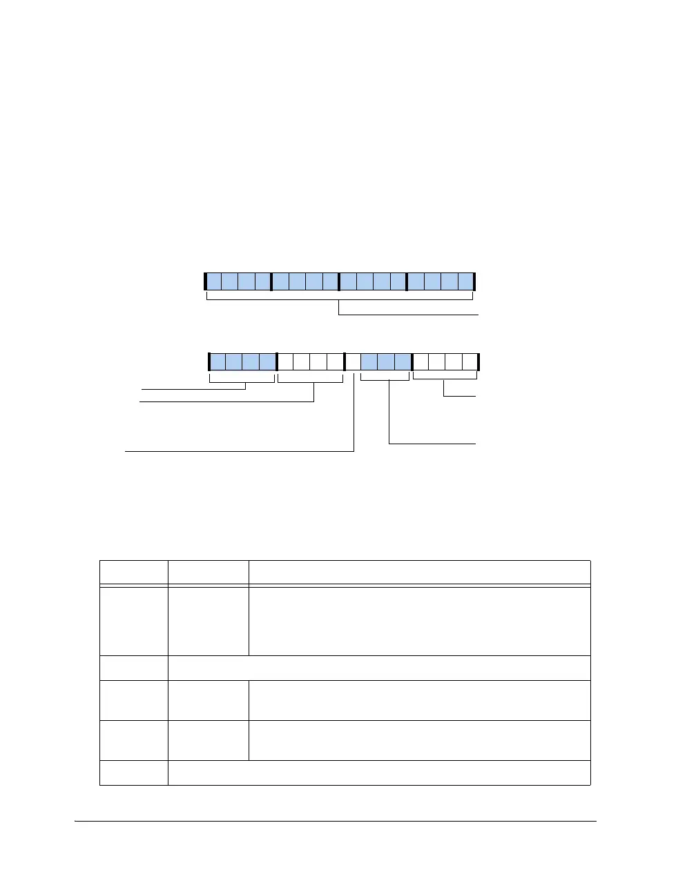
SPI Port Flags Registers (SPIFLG, SPIFLGB)
These registers’ addresses are 0x1001 and 0x2801 (SPIFLGB). The reset
value is 0x0F80.The SPIFLG and SPIFLGB registers, shown in Figure A-25
and described in Table A-12, are used to enable individual SPI slave-select
lines when the SPI is enabled as a master.
Figure A-25. SPIFLG, SPIFLGB Registers
Table A-12. SPIFLG, SPIFLGB Register Bit Descriptions
Bit Name Description
3–0 DSxEN (3-0) SPI Device Select Enable. Enables or disables the corresponding
flag as a flag output to be used for SPI slave-select.
0 = Disable
1 = Enable
6–4 Reserved
7ISSSInput Service Select. This read-only bit reflects the status of the
slave-select input pin.
11–8 SPIFLGx
(3-0)
SPI Device Select Control. Selects (if cleared, = 0) a correspond-
ing flag output to be used for an SPI slave-select.
12–31 Reserved
31 30 29 28 27 26 24 23 22 21 20 19 18 17 16
0000000000000000
Reserved
15 14 13 12 11 10 8 7 6 5 4 3 2 1 0
0000011110000000
Reserved
SPIFLGx
DSxEN
SPI Device Select Enable
1=Enable
0=Disable
Reserved
SPI Device Select Control
1=Disable
0=Enable
ISSS
Status of Input Slave Select Pin
24
9
SPIFLG (0x1001)
SPIFLGB (0x2801)
 Loading...


