UART Control and Status Registers
A-126 ADSP-21368 SHARC Processor Hardware Reference
Scratch Registers (UARTxSCR)
The contents of the 8-bit UART scratch registers (UARTxSCR shown in
Figure A-55) is reset to 0x00. It is used for general-purpose data storage
and does not control the UART hardware in any way.
Mode Registers (UARTxMODE)
The UART mode registers control miscellaneous settings as shown in
Figure A-56 and described Table A-48.
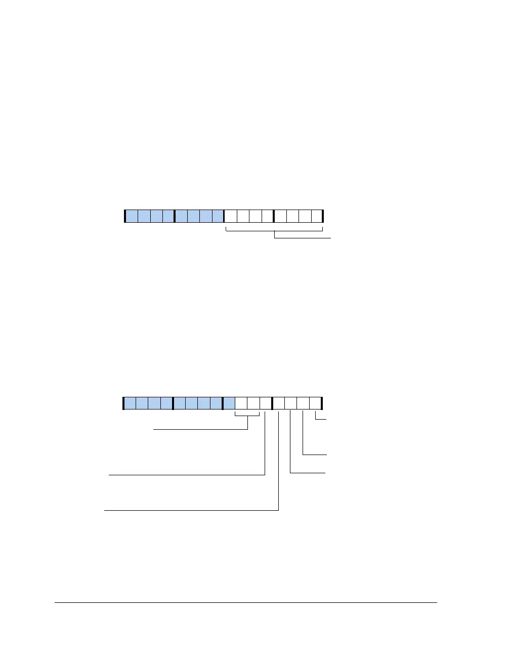
Figure A-55. UART Scratch Registers
Figure A-56. UART Mode Registers
Scratch[7:0]
UART0SCR (0x3C07)
UART1SCR (0x4007)
15 14 13 12 11 10 9 8 7 6 5 4 3 2 1 0
0000000000000000
15 14 13 12 11 10 9 8 7 6 5 4 3 2 1 0
0000000000000000
UARTPACK
UARTPKSYN
Packing Enable
0=No pack
1=Pack
Synchronize Data Packing in Rx
UART0MODE (0x3C04)
UART1MODE (0x4004)
UARTRX9
Enable 9-Bit Tx in Receiver
0=I/O mode
1=9-bit transmission in receiver
UARTAEN
Enable Address Detect (if Rx9 = 1)
0=Disable address detection
1=Enable address detection
UARTPST0, UARTPST1
Pin Status
11=UART output is high in disabled state (default)
00=UART output is low in disabled state
01/10=UART output is three-stated in disabled state
UARTTX9
Enable 9-Bit Tx in Transmitter
0=I/O mode
1=9-bit transmission in transmitter
 Loading...


