Setting AMI Modes
3-24 ADSP-21368 SHARC Processor Hardware Reference
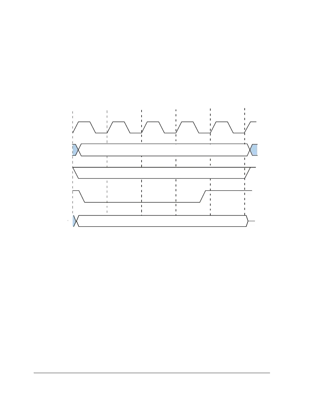
The address, data (if a write), and bank select (if in banked external mem-
ory) remain unchanged and are driven for one or more cycles after the
read or write strobes are deasserted. Figure 3-5 demonstrates a hold time
cycle appended to an asynchronous write access (
EBxWS = 011).
Setting AMI Modes
The AMICTLx registers control the asynchronous memory interface’s oper-
ating mode and the
AMISTAT register provides status information.
Table A-5 on page A-18 lists all the bits in the
AMICTLx registers and
Figure A-7 on page A-20 shows all the bits in the AMISTAT register.
• For information on using DMA through the external port, see
“External Port DMA” on page 2-35.
• For information on using external port interrupts, see “Inter-
rupt-Driven I/O” on page 2-6.
Figure 3-5. Hold Time Cycle Example
12 3 4 5
SDCLK
ADDRESS 23
-
0
MSx
WR
DATA 31
-
0
TIME
WRITE
 Loading...


