ADSP-21368 SHARC Processor Hardware Reference A-121
Register Reference
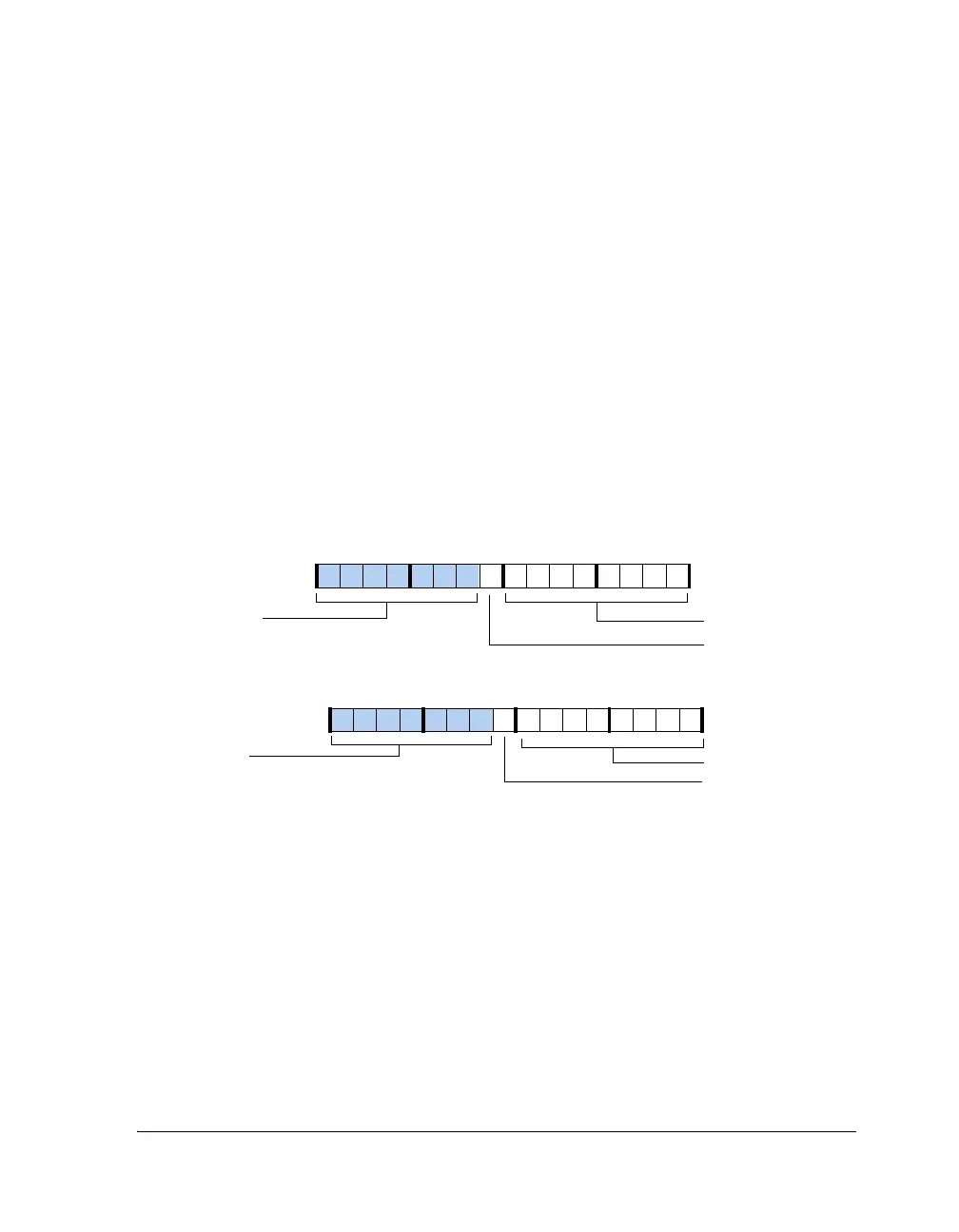
Transmit Hold Registers (UARTxTHR)
In no pack mode (default), only the lower byte of these registers is used—
all other bits are zero-filled. However in pack mode, both the high and
low bytes are used. The TX9D and RX9D are the 9th bit in 9-bit transmission
mode. These registers are mapped to the same address as the UARTxRBR and
UARTxDLL registers. A write to the UART transmit holding registers
(UARTxTHR) initiates the transmit operation.
To access UARTxTHR (shown in Figure A-50), the UARTDLAB bit in UARTxLCR
must be cleared. When the UARTDLAB bit is cleared, writes to this address
target the UARTxTHR registers, and reads from this address return the UAR-
TxRBR
registers.
Figure A-50. UART Transmit Holding Registers (Packing Enabled)
31 30 29 28 27 26 25 24 23 22 21 20 19 18 17 16
0000000000000000
Higher Byte
UART0THR (0x3C00)
UART1THR (0x4000)
15 14 13 12 11 10 9 8 7 6 5 4 3 2 1 0
0000000000000000
Lower Byte
TX9D0
TX9D1
Zero-Filled
Zero-Filled
 Loading...


