Frame Sync Output Synchronization With an External Clock
13-8 ADSP-21368 SHARC Processor Hardware Reference
Frame Sync
For a given frame sync, the output is determined by the following:
• Divisor. A 20-bit divisor of the input clock that determines the
period of the frame sync. When set to 0 or 1, the frame sync oper-
ates in bypass mode, otherwise it operates in normal mode.
• Phase. A 20-bit value that determines the phase relationship
between the clock output and the frame sync output. Settings for
phase can be anywhere between 0 to DIV – 1.
• Pulse width. A 16-bit value that determines the width of the fram-
ing pulse. Settings for pulse width can be 0 to
DIV – 1. If the pulse
width is equal to 0 or the frame sync is even, then the actual pulse
width of the output frame sync is:
For odd divisors the actual pulse width of the output frame sync is:
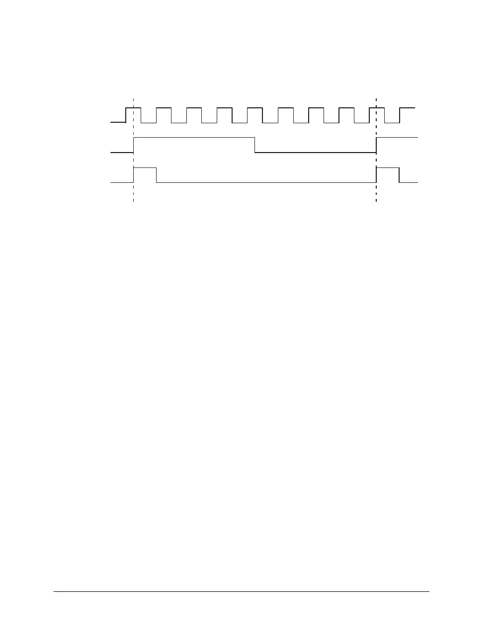
Figure 13-2. Clock Output Synchronization With External Clock
FSA OUTPUT
MCLK
EXT CLK
Pulse Width
FrameSyncDivisor
2
----------------------------------------------
=
Pulse Width
FrameSyncDivisor 1–
2
-------------------------------------------------------
=
 Loading...

