SPI Interface Signals
6-6 ADSP-21368 SHARC Processor Hardware Reference
SPI Slave Select Input (SPIDS
)
The SPIDS signal is the serial peripheral interface device select input signal.
This active low signal is used to enable a processor that is configured as a
slave device. As an input only pin, SPIDS behaves like a chip select, and is
driven by the master device for the slave devices. When the processor is
the SPI master in a multimaster environment, the SPIDS pin acts as an
error signal. In multimaster mode, if the SPIDS input signal of a master is
asserted (driven low), a multimaster error condition occurs which means
that another device is also trying to be the master device. For a single-mas-
ter, multiple-slave configuration, the SPIDS signal of the master device
must be tied high, or the SPI port allows this signal to be disabled and
used as a GPIO input.
SPI Flag Signals (SPIFLG3-0)
These signals are driven by the processor as an SPI master to the SPIDS pin
of the slave. When
CPHASE = 0, the SPI port hardware controls the
device-select signal automatically (determined by the DSxEN bits in the
SPIFLG register). Setting CPHASE = 1 requires these signals be manually
controlled by the software through the
SPIFLGx bits in the SPIFLG and
SPIFLGB registers. The SPIFLGx bits are ignored when CPHASE = 0.
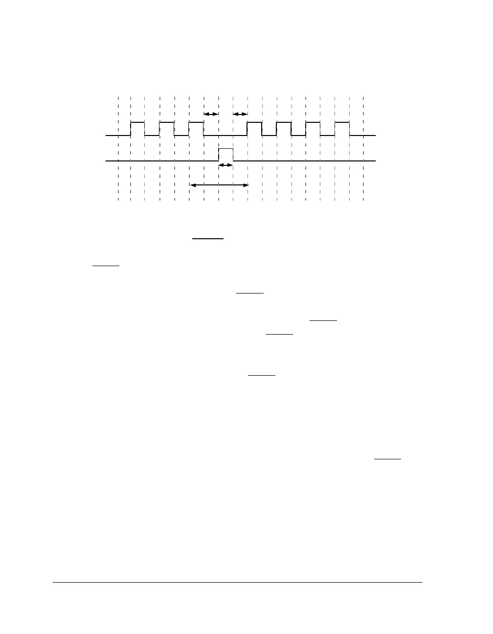
Figure 6-3. SPICLK Timing
SPICLK
CPHASE =0
T1 T 2
T3
T4
SPIDS
TO SL AVE
 Loading...


