Input Data Port Registers
A-66 ADSP-21368 SHARC Processor Hardware Reference
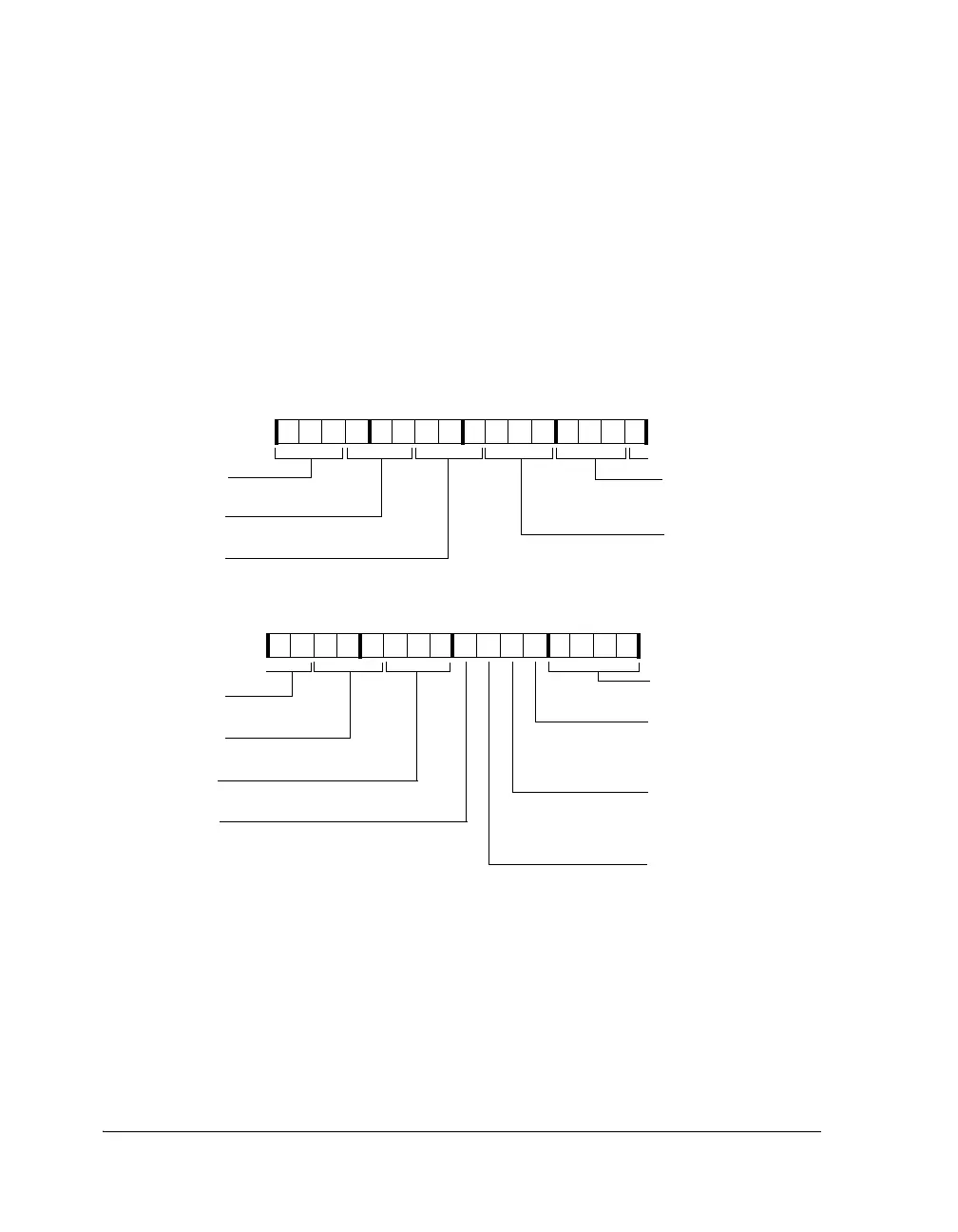
Input Data Port Control Register 0 (IDP_CTL0)
Use the IDP_CTL0 registers to configure and enable the input data port and
each of its channels. This register is shown in Figure A-27 and described
in Table A-16.
L
The IDP may also be routed through the DAI using its bits. For
more information, see “DAI/DPI Registers” on page A-109.
Figure A-27. IDP_CTL0 Register
31 30 29 28 27 26 25 24 23 22 21 20 19 18 17 16
0000000000000000
15 14 13 12 11 10 9 8 7 6 5 4 3 2 1 0
0000000000000000
IDP_SMODE7
Buffer Hang Disable
0 = Core hang is enabled
1 = Core hang is disabled
IDP_SMODE6
IDP_SMODE3
IDP_SMODE4
IDP_SMODE5
IDP_SMODE2
IDP_SMODE1
IDP_ENABLE
IDP_NSET
IDP_BHD
IDP_DMA_EN
IDP_CLROVER
IDP_CTL0 (0x24B0)
Channel 7 Serial Mode Select
Channel 6 Serial Mode Select
Channel 3 Serial
Mode Select
Channel 4 Serial
Mode Select
Channel 5 Serial Mode Select
Channel 2 Serial Mode Select
Channel 1 Serial Mode Select
Global IDP Enable
1=Enable all IDP channels
0=IDP disabled
Number of FIFO Entries
IDP_SMODE0
Channel 0 Serial Mode Select
Global IDP DMA Enable
0=IDP DMA disabled
1=IDP DMA enable
Clear FIFO Overflow (WO)
1=Clear overflow
 Loading...


