SPI Interface Signals
6-4 ADSP-21368 SHARC Processor Hardware Reference
through their
SPIDS pins. The SPI ports also provide a mechanism to dis-
able the MISO pin for multimaster systems where the slave SHARC
processor does not need to transmit any data to the master.
SPI Interface Signals
The SPI uses a 4-wire protocol to enable full-duplex serial communica-
tion. This section describes the signals used to connect the
ADSP-21367/8/9 and ADSP-2137x processor’s SPI ports in a system that
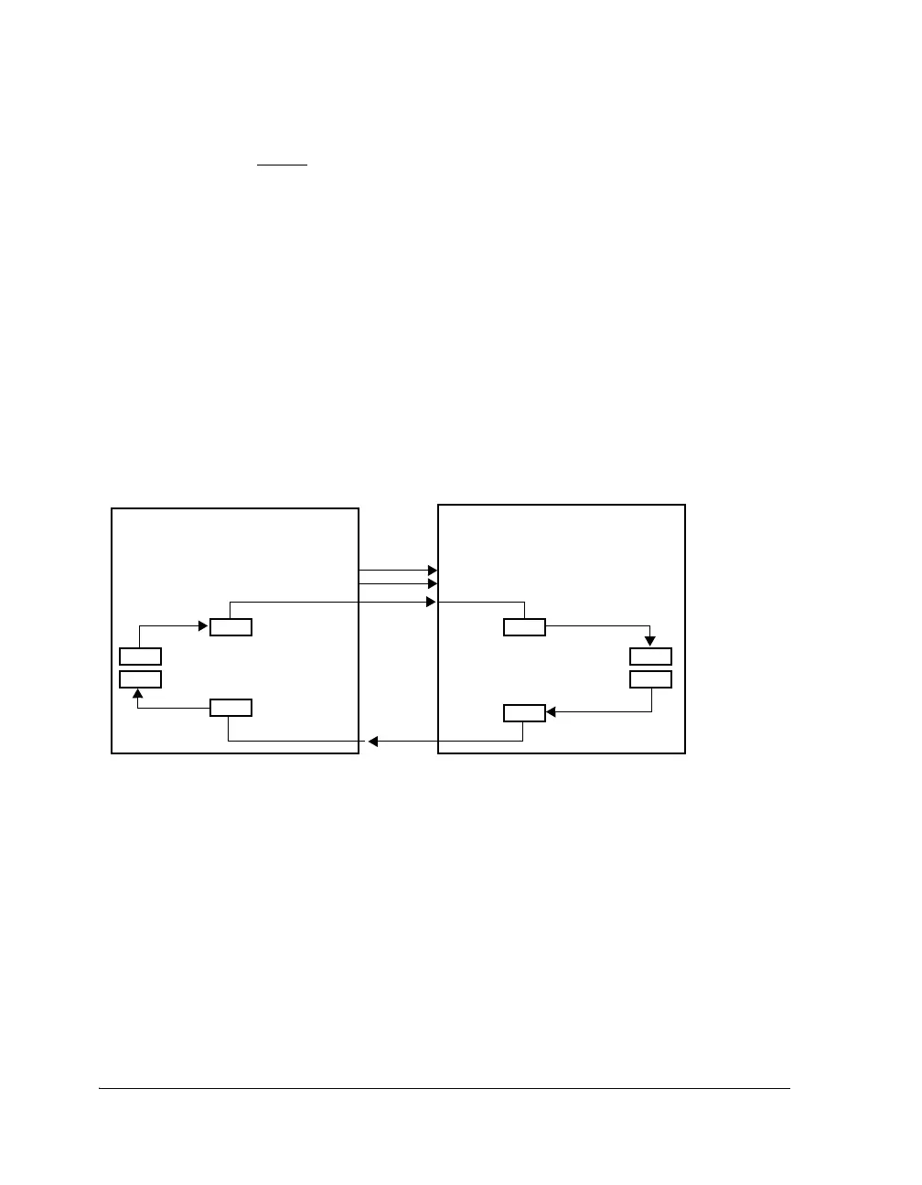
has multiple devices. Figure 6-2 shows the master-slave connections
between two devices.
SPI Clock Signal (SPICLK)
The SPICLK signal is the serial peripheral interface clock signal. This con-
trol signal is driven by the master and regulates the flow of data bits. The
master may transmit data at a variety of baud rates. One data bit is trans-
ferred for each SPICLK cycle.
Figure 6-2. Master-Slave Interconnections
ADSP-213xx
SPI-Compatible Master Device
SPICLK
FLAG
N
MOSI
TXSR
TXSPI
RXSPI
RXSR
MISO
ADSP-213xx
SPI-Compatible Slave Device
SPICLK
SPIDS
MOSI
TXSR
TXSPI
RXSPI
RXSR
MISO
 Loading...


