ADSP-21368 SHARC Processor Hardware Reference 3-87
External Port
Bus Mastership Time-out
In either the fixed or rotating priority scheme, systems may need to limit
how long a bus master can retain the bus. This is accomplished by forcing
the bus master to deassert its
BRx line after a specified number of CLKIN
cycles and giving the other processors a chance to acquire bus mastership.
To set up a bus master time-out, a program must load the bus time-out
maximum (BMAX register, address = 0x180D, Figure 3-17) with the maxi-
mum number of CLKIN cycles (minus 2) that allows the processor to retain
bus mastership. This equation is shown below.
BMAX = (maximum number of bus mastership CLKIN cycles) – 2
The minimum value for
BMAX is 2, which lets the processor retain bus mas-
tership for four CLKIN cycles. Setting BMAX=1 is not allowed. To disable the
bus master time-out function, set
BMAX=0.
Each time a processor acquires bus mastership, its bus time-out counter
(
BCNT register, address = 0x180E) is loaded with the value in BMAX. The
BCNT is then decremented in every CLKIN cycle in which the master per-
forms a read or write over the bus and any other (slave) processors are
requesting the bus. Any time the bus master deasserts its BRx line, BCNT is
reloaded from BMAX.
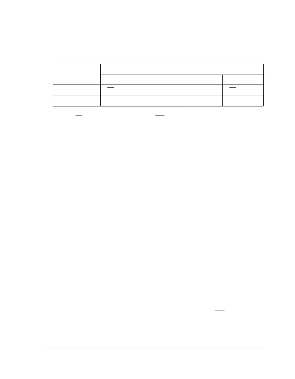
4 3-BR M1 2-BR
5
3
1-BR 23M
1 The following symbols appear in these cells: 1-3 = assigned priority, M = bus mastership (in that
cycle), BR
= requesting bus mastership with BRx
2 Initial priority assignments
3 Final priority assignments
Table 3-31. Rotating Priority Arbitration Example (Cont’d)
Cycle Number
Hardwired Processor IDs and Priority
1
ID1 ID2 ID3 ID4
 Loading...


