Making Connections in the SRUs
4-52 ADSP-21368 SHARC Processor Hardware Reference
There are three separate groups of connections that are used in SRU2. The
following sections summarize each.
Group A Connections—Input Routing Signals
Group A is used to route the 14 external pin signals, timer, and UART
outputs to the inputs of the other peripherals. Unlike the DAI SRU, all
functions, such as serial clock and data, are combined into the same group
A connections.
All clock inputs that are not used should be set to logic low. The registers
and input signals for group A are summarized in Figure 4-41 through
Figure 4-46 and Table 4-11.
DPI_06 SPIFLG1 DPI_13 TIMER0_O
DPI_07 SPIFLG2 DPI_14 TIMER1_O
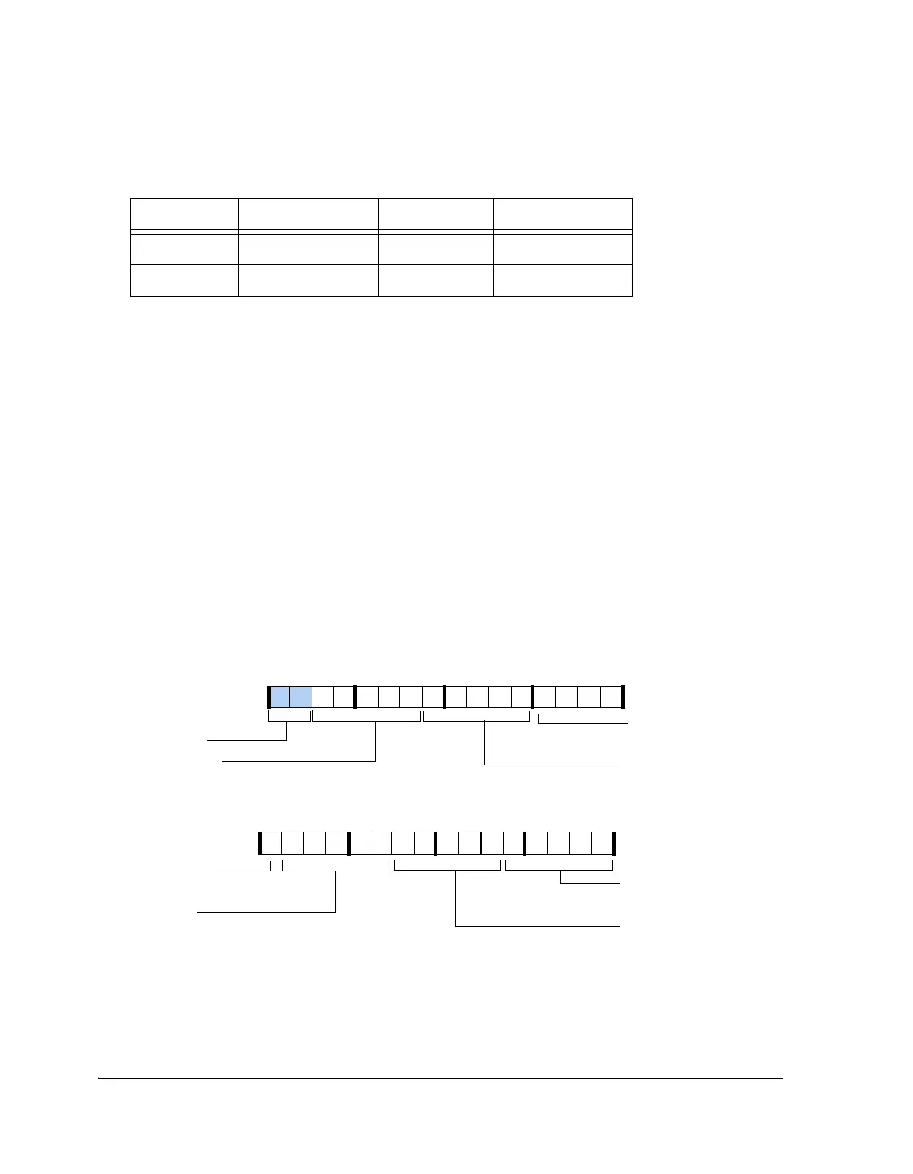
Figure 4-41. SRU2_INPUT0 Register
Table 4-10. DPI/SRU2 Default Configuration (Cont’d)
Pin Number Signal Pin Number Signal
31 30 29 28 27 26 25 24 23 22 21 20 19 18 17 16
0000000000000001
Reserved
15 14 13 12 11 10 9 8 7 6 5 4 3 2 1 0
0000101000110001
SPIB_MISO_I
SPI B MISO Input
SPI_CLK_I
SPI Clock Input
SPIB_MOSI_I
SPI B MOSI Input
SPI_DS_I
SPI Device Select Input
SPI_MISO_I
SPI MOSI Input
SPI_MOSI_I
SPI MISO Input
SRU2_INPUT0
(0x1C00)
SPI_CLK_I
SPI Clock Input
Reset = 0x00021462
 Loading...


