S/PDIF Transmitter
9-14 ADSP-21368 SHARC Processor Hardware Reference
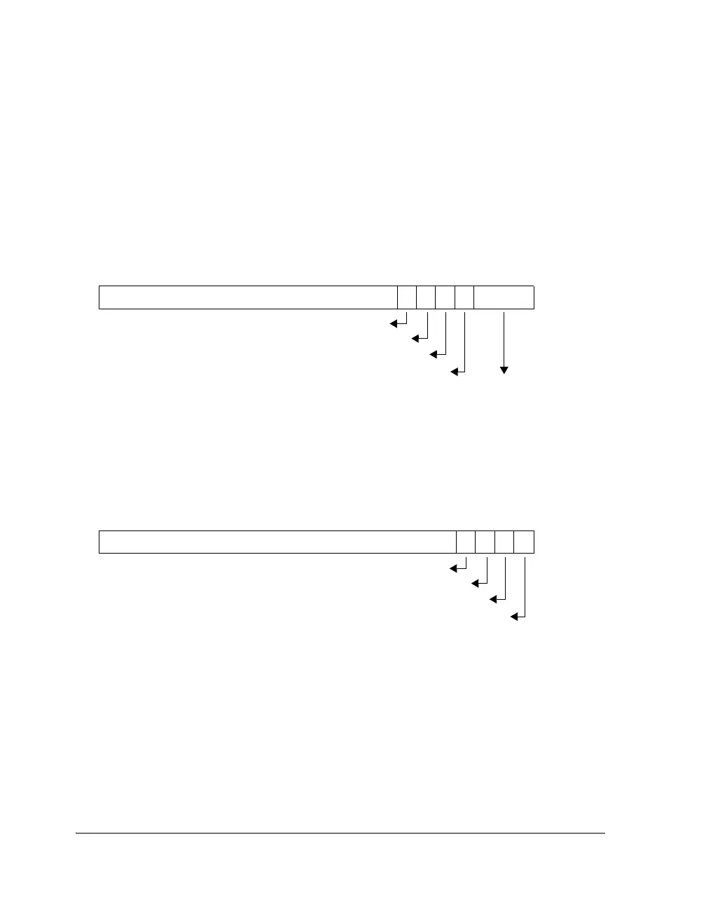
Structure of the Serial Input Data
Figure 9-5 shows the format of data that is sent to the S/PDIF transmitter
using a 24-bit I
2
S interface. The upper 24 bits (bits 8 through 31) contain
the audio data. Bits 3–7 are used to transmit status information and to
generate preambles and or headers. Bits 0 through 3 are empty.
L
When I
2
S format is used with 20-bit or 16-bit data, the audio data
should be placed from the MSB of the 24-bit audio data.
Figure 9-5. Data Packing for I
2
S and Left-Justified Format
Figure 9-6. Data Packing for Right-Justified Format, 24 Bits
Bits 31–8: 24-Bit Audio Data 7654BITS 3–0
Padding (zero)
BLK_STRT
Channel Status
User Data
Validity Bit
Bits 27–4: 24-Bit Audio Data
3210
Channel Status
User Data
Validity Bit
Block Status
 Loading...


