ADSP-21368 SHARC Processor Hardware Reference A-115
Register Reference
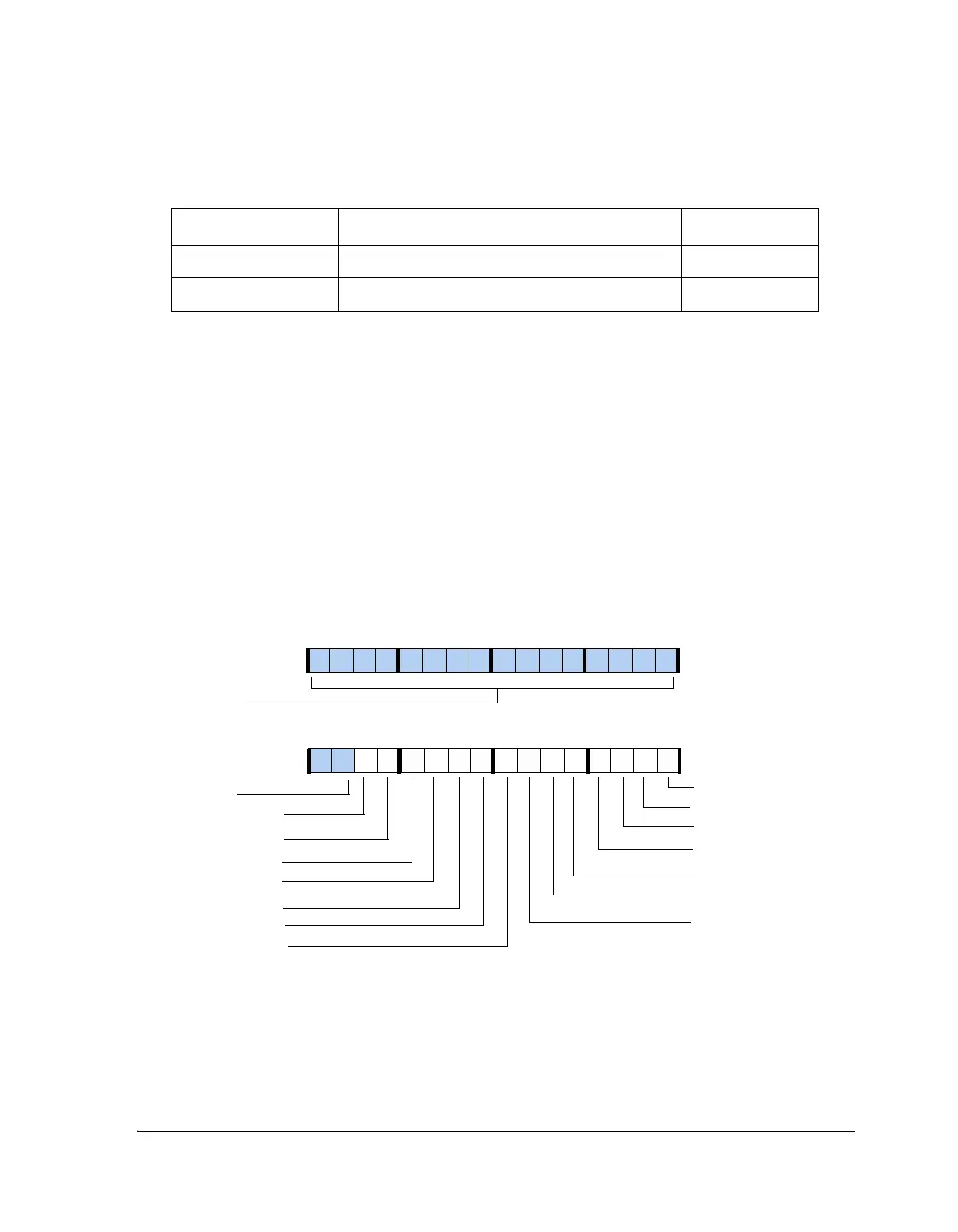
DPI Resistor Pull-up Enable Register
(DPI_PIN_PULLUP)
This 16-bit read/write register is shown in Figure A-45. Bits 13–0 of this
register control the enabling/disabling 22.5 KΩ pull-up resistor on
DPI_P0[13:0]. Setting a bit to 1 enables a pull-up resistor on the corre-
sponding pin. After RESET, the value of this register is 0xFFFFF, which
means pull-ups are enabled on all 14 DPI pins.
DAI_IRPTL_RE Rising Edge Interrupt Mask Register 0x2481
DAI_IRPTL_FE Falling Edge Interrupt Mask Register 0x2480
Figure A-45. DPI_PIN_PULLUP Register
Table A-46. DAI Interrupt Registers (Cont’d)
Register Description Address
15 14 13 12 11 10 9 8 7 6 5 4 3 2 1 0
1001111111111111
DPI_P14_PULLUP
DPI_P13_PULLUP
DPI_P12_PULLUP
DPI_P01_PULLUP
DPI_P02_PULLUP
DPI_P03_PULLUP
DPI_P04_PULLUP
DPI_P05_PULLUP
DPI_P06_PULLUP
DPI_P11_PULLUP
DPI_P10_PULLUP
DPI_P09_PULLUP
DPI_P07_PULLUP
DPI_P08_PULLUP
DPI_PIN_PULLUP (0x1C30)
31 30 29 28 27 26 25 24 23 22 21 20 19 18 17 16
0000000000000000
Reserved
Reserved
 Loading...


