ADSP-21368 SHARC Processor Hardware Reference A-125
Register Reference
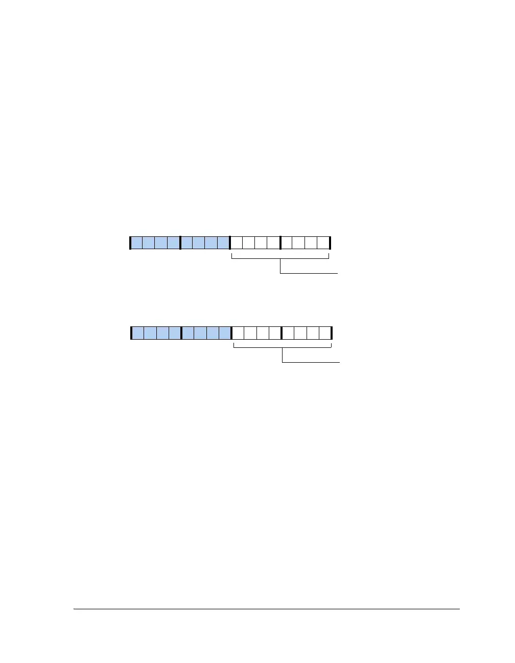
Divisor Latch Registers (UARTxDLL, UARTxDLH)
The bit rate is characterized by the system clock (SCLK) and the 16-bit
divisor. The divisor is split into the UART divisor latch low byte register
(UARTxDLL) and the UART divisor latch high byte register (UARTxDLH),
both shown in Figure A-54.
The UARTxDLL registers are mapped to the same address as the UARTxTHR
and UARTxRBR registers. The UARTxDLH registers are mapped to the same
address as the interrupt enable registers (
UARTxIER). The UARTDLAB bit in
the UARTxLCR register must be set before the UART divisor latch registers
can be accessed.
Figure A-54. UART Divisor Latch Registers
Divisor Latch Low Byte[7:0]
Divisor Latch High Byte[15:8]
15 14 13 12 11 10 9 8 7 6 5 4 3 2 1 0
1000000000000000
15 14 13 12 11 10 9 8 7 6 5 4 3 2 1 0
0000000000000000
UART0DLL (0x3C00)
UART1DLL (0x4000)
UART0DLL (0x3C01)
UART1DLL (0x4001)
 Loading...


