UART Control and Status Registers
11-12 ADSP-21368 SHARC Processor Hardware Reference
L
The 16-bit divisor formed by the UARTxDLH and UARTxDLL registers
resets to 0x0001, resulting in the highest possible clock frequency
by default. If the UART is not used, disabling the UART clock
saves power (see bits 13 and 14 in the “Power Management Con-
trol Register (PMCTL)” on page A-170). The UARTxDLH and
UARTxDLL registers can be programmed by software before or after
turning on the clock.
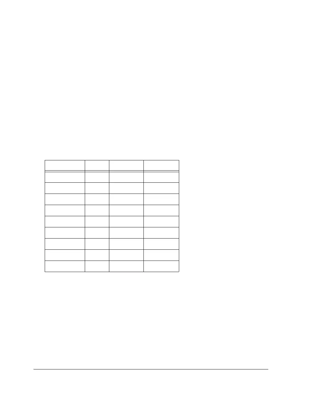
Table 11-2 provides example divide factors required to support most stan-
dard baud rates.
L
Careful selection of PCLK frequencies, that is, even multiples of
desired baud rates, can result in lower error percentages.
UARTxSCR Register
The contents of the 8-bit UART scratch register (UARTxSCR) is reset to
0x00. It is used for general-purpose data storage and does not control the
UART hardware in any way.
Table 11-2. UART Baud Rate Examples With 100 MHz PCLK
Baud Rate DL Actual % Error
2400 2604 2400.15 0.006
4800 1302 4800.31 0.007
9600 651 9600.61 0.006
19200 326 19,171.78 0.147
38400 163 38,343.56 0.147
57600 109 57,339.45 0.452
115200 54 115,740.74 0.469
921,600 7 892,857.14 3.119
6,250,000 1 6,250,000 –
 Loading...


