Serial Port DMA
2-40 ADSP-21368 SHARC Processor Hardware Reference
4. Once the read count completes, the delay line DMA access is com-
plete and the DMA complete interrupt is generated. Note that if
chaining is enabled, the interrupt is generated based on the
PCI bit
setting. For more information on the PCI bit, see “Interrupt-Driven
I/O” on page 2-6.
Serial Port DMA
The serial ports support standard as well as chained DMA.
Setting Up and Starting Chained DMA
To set up and initiate a chain of DMA operations, use these steps:
1. Set up all TCBs in internal memory.
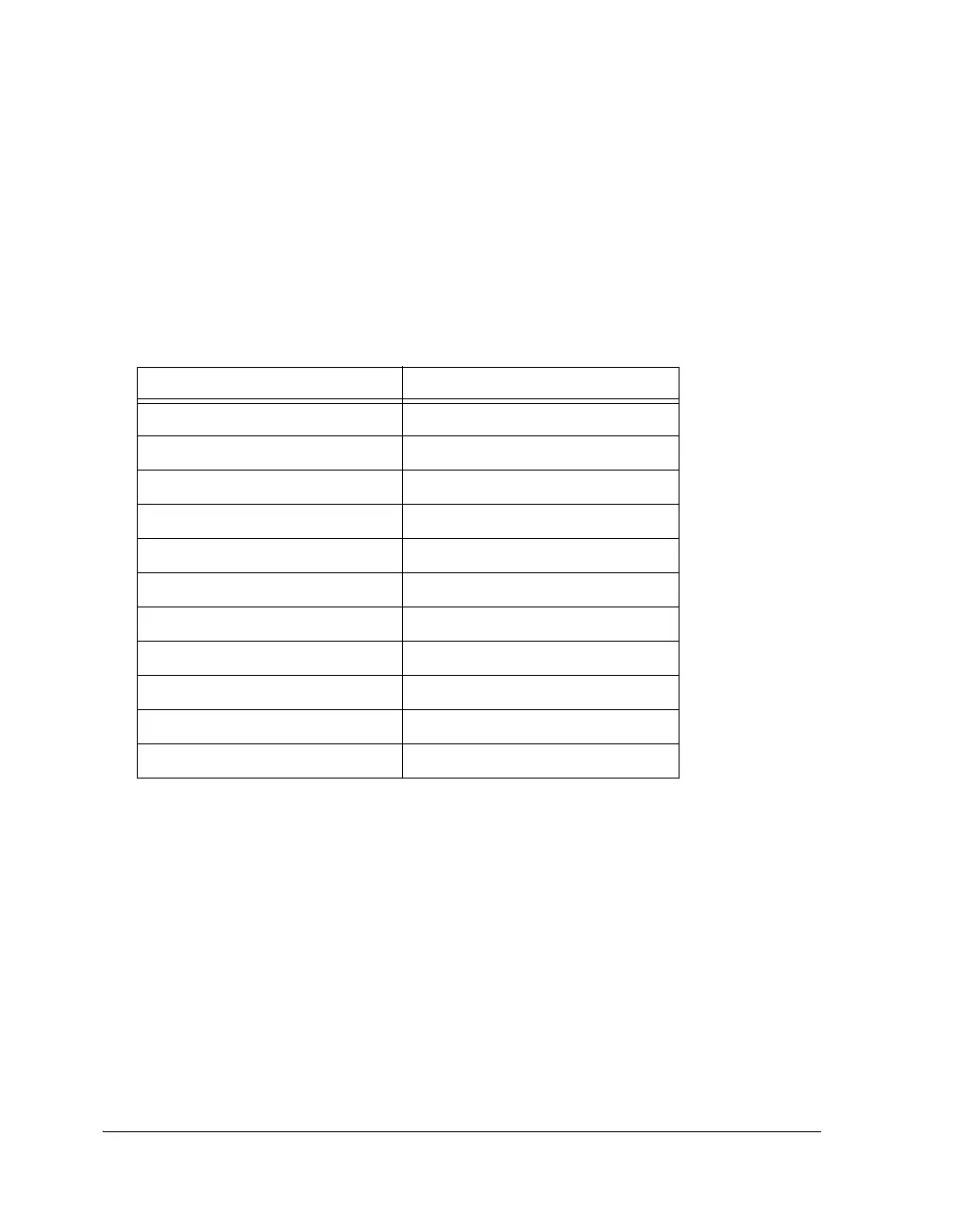
Table 2-11. Chain Pointer Loading Sequence (Delay Line DMA)
Address Register Value
EPCP[18:0] EPII (Write Index)
EPCP[18:0] – 0x1 EPIM
EPCP[18:0] – 0x2 EPIC (Write Count)
EPCP[18:0] – 0x3 EPEI
EPCP[18:0] – 0x4 EPEM
EPCP[18:0] – 0x5 EPEB
EPCP[18:0] – 0x6 EPEL
EPCP[18:0] – 0x7 EPRI
EPCP[18:0] – 0x8 EPRC
EPCP[18:0] – 0x9 EPTP
EPCP[18:0] – 0xA EPCP
 Loading...


