DAI/DPI Registers
A-112 ADSP-21368 SHARC Processor Hardware Reference
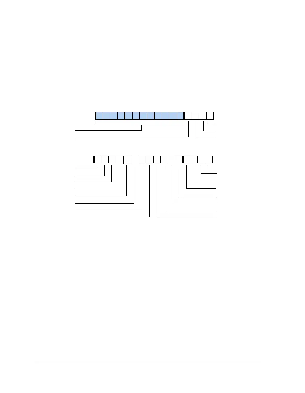
DAI Pin Buffer Status Register (DAI_PIN_STAT)
This 20-bit, read-only register is shown in Figure A-43. Bits 19–0 of this
register indicate the status of DAI_PB[20:1]. Reads from bits 31–20 always
return 0. This register is updated at one-half the core clock rate.
DAI Interrupt Controller Registers
The DAI contains its own interrupt controller that indicates to the core
when DAI audio peripheral related events have occurred. Since audio
events generally occur infrequently relative to the SHARC core, the DAI
interrupt controller reduces all of its interrupts onto two interrupt signals
within the core’s primary interrupt systems—one mapped with low prior-
ity and one mapped with high priority. This architecture allows programs
to indicate priority broadly. In this way, the DAI interrupt controller reg-
isters provide 32 independently configurable interrupts labeled
DAI_INT[31:0], respectively.
Figure A-43. DAI_PIN_STAT Register
31 30 29 28 27 26 25 24 23 22 21 20 19 18 17 16
1000000000000111
15 14 13 12 11 10 9 8 7 6 5 4 3 2 1 0
1111111111111111
Reserved
DAI_PB16
DAI_PB20
DAI_PB19
DAI_PB18
DAI_PB17
DAI_PB15
DAI_PB14
DAI_PB13
DAI_PB12
DAI_PB01
DAI_PB02
DAI_PB03
DAI_PB04
DAI_PB05
DAI_PB06
DAI_PB11
DAI_PB10
DAI_PB09
DAI_PB07
DAI_PB08
DAI_PIN_STAT (0x24B9)
 Loading...


