Interrupt Vector Tables
B-4 ADSP-21368 SHARC Processor Hardware Reference
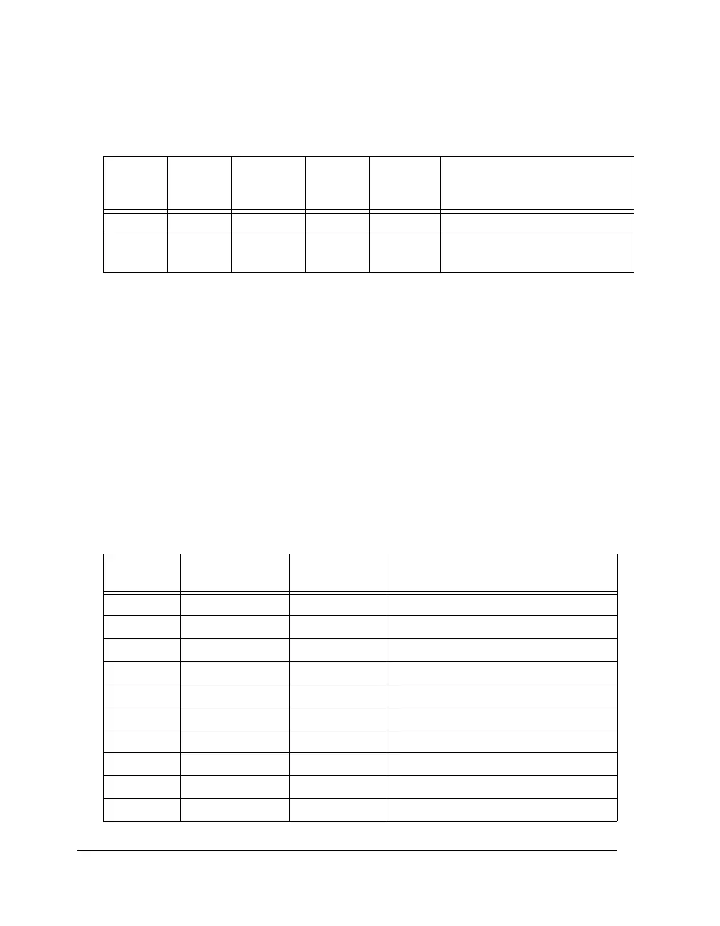
Interrupt Priorities
The ADSP-21367/8/9 and ADSP-2137x SHARC processors support 19
prioritized IOP interrupts which are shown in Table B-3. Table B-3 also
lists the value corresponding to each interrupt source. To route an IOP
interrupt source to a corresponding programmable interrupt location, see
“Peripheral Interrupt Priority Control Registers” on page A-164.
40 IRPTL 30 0xA0 SFT2I User software interrupt 2
41 IRPTL 31 0xA4 SFT3I User software interrupt 3
LOWEST PRIORITY
1 If configured for internal ROM boot mode, then the base address for the interrupt vector table is
the starting address of internal ROM or 0x00080000.
2 These interrupts have options to unmask at reset. Therefore, the peripherals that boot the processor
should be allocated these interrupts: P1I, P9I.
Table B-3. Interrupt Selection Values
No Interrupt Source Interrupt Select
Value (5-Bits)
Comments
1 DAI1 0x00 DAI high priority interrupt
2 SPIAI 0x01 SPIA high priority interrupt
3 GPTMR0I 0x02 General-purpose IOP timer 0 interrupt
4 SP1I 0x03 Serial port 1 interrupt
5 SP3I 0x04 Serial port 3 interrupt
6 SP5I 0x05 Serial port 5 interrupt
7 SP0I 0x06 Serial port 0 interrupt
8 SP2I 0x07 Serial port 2 interrupt
9 SP4I 0x08 Serial port 4 interrupt
10 EP0I 0x09 External port channel 0 interrupt
Table B-2. Interrupt Vector Addresses (Cont’d)
Interrupt
Number
Register IRPTL/
LIRPTL/
MASK Bit#
Vector
Address
Interrupt
Name
Function
 Loading...


